Leaving No Pixel Behind: New Render Target Cache, 3x3 Resolution Scaling & Three Years in Xenia’s GPU Emulation
Note: This update renames some commonly used config options such as d3d12_edram_rov and d3d12_resolution_scale. Please check the end of this post to see if you need to change anything in your config.
Hello again world! It’s Triang3l, the graphics programmer of Xenia, with a new blog post — after almost 6 years since the last message, and while we’ve been silent here for all that time, it has been long enough for a lot of great things to happen in Xbox 360 emulation!
Back in 2015, the list of games that could be considered “playable” was still pretty tiny — mostly including not very technically complex, primarily 2D games. Most games back then, if gameplay could even be reached in them, exhibited severe graphical glitches, ran at frame rates well below what can be considered not even “comfortable”, but just “motion” at all, and sometimes had CPU-side progression-blocking issues.
Now, as of April 27, 2021, the game compatibility tracker, out of 1404 total tiles reported, contains the total of 1041 games — or 74% of the whole library of tested games — listed as playable or in-game, with 221 of them being playable near-flawlessly, and most games are able to reach their target frame rate on contemporary PC hardware! Xenia has constantly been evolving in all its aspects — the OS reimplementation, the CPU, audio processing, and of course emulation of the Xbox 360’s Xenos graphics processing unit.
GPU emulation, in particular, has been a very fun adventure throughout all of the development of Xenia. A GPU is an extremely complex device, encompassing many different kinds of functionality on all stages of the graphics pipeline. And the Xbox 360’s GPU specifically was a playground for experiments — it was developed near the end of the Direct3D 9 era, but still before Direct3D 10, and contained many features not standardized or even available at all on the PC, but when they ended up on the PC, the actual implementation could be significantly different; it also included completely unique features. Over the years, we’ve been trying various approaches to emulation of different components of the GPU, including a complete redesign of the entire GPU emulation architecture in 2018.
This time, we’re releasing a complete rewrite of the implementation of the most customized part of the Xbox 360 GPU — color output and depth/stencil buffer handling — massively increasing speed in the conventional (non-ROV) render target implementation, adding an option that may somewhat improve its accuracy, enabling true MSAA instead of supersampling, as well as the addition of 3x3 resolution scaling on both the ROV and the non-ROV pixel output paths!
In addition, in this post, we’re giving a huge write-up of what we’ve been doing in GPU emulation in the last 3 years, covering all the challenges that we’ve faced in the emulation of the console’s super-fast eDRAM and the approaches we’ve tried, and why it’s such a big performance eater in emulation — including all the data sharing and custom pixel format issues; as well emulation of the unified memory and textures!
Disclaimer: Information about the interface and the behavior of the Xbox 360’s GPU was obtained from publicly available sources, such as Qualcomm’s Code Aurora Forum header file release and the unofficial Freedreno driver (as the Adreno 200 GPU is heavily based on the Xenos), XNA Game Studio 3.1 and its documentation on MSDN, presentations and papers released by game developers and Microsoft, and reverse engineering of games, consoles and Adreno 2xx-powered mobile devices. The writer of this post has never used the Xbox 360 XDK for any purpose, and contributions based on information obtained from the XDK are not allowed. For this reason, this post is also not guaranteed to provide 100% accurate (or free of factual errors) information about the console’s behavior.
A long time ago, in a renderer far, far behind…
(or are we referencing the wrong movie in a chapter about a Vulkan GPU backend?…)
To understand why render targets are such an important — and quite complicated — part of the Xbox 360’s GPU to emulate, let’s go back to this beautiful Halo installation you might have visited in 2018:
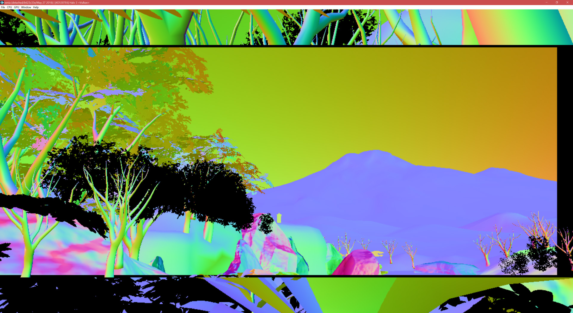
Emulate the rainbow! (Halo 3, by Bungie, screenshot provided by CovertSlinky)
What you can see here is the G-buffer containing pixel normals, with some areas — the cutscene letterbox — not cleared correctly, and some remains of another rendering pass involving the foliage.
But why would a buffer populated very early on in the rendering pipeline of the game, used only for lighting purposes, be sent to the final output?
Let’s look at the way framebuffers (also known as “render targets”) are managed in a PC game running on a PC graphics API such as Direct3D 9 or 11 or OpenGL.
A simplified rendering pipeline with deferred lighting has two passes:
- G-buffer filling pass — writing normals, diffuse color, glossiness and depth.
- Lighting and composition pass — reading normals, diffuse/glossiness and depth, writing the final color.
On the PC Direct3D 9, setup and rendering is performed as follows:
- Create the device with a back buffer 8-bits-per-channel (8.8.8.8) surface for final output.
- Create the normals 10-bits-per-channel (10.10.10.2) texture.
- Create the diffuse/glossiness 8-bits-per-channel (8.8.8.8) texture.
- Create the depth texture.
- When drawing a frame:
- Bind the normals texture’s surface as render target 0.
- Bind the diffuse/glossiness texture’s surface as render target 1.
- Bind the depth texture’s surface as the depth render target.
- Draw the geometry to fill the G-buffers.
- Bind the back buffer surface as render target 0.
- Bind the normals texture to the pixel shaders.
- Bind the diffuse/glossiness texture to the pixel shaders.
- Bind the depth texture to the pixel shaders.
- Draw the lighting pass and things like UI.
- Present the back buffer to the screen.
Normally, when you create a texture on an older, high-level-of-abstraction PC graphics API like Direct3D 9, you only specify its properties such as format, size, mip count, usage purposes — but memory is allocated somewhere internally by the driver/OS for it. The app only gets an opaque handle — such as a IDirect3DTexture9 pointer — that can be used to reference the texture in various API operations, such as binding the texture to shaders for sampling from it, setting it as the current render target, copying between the texture and other textures of usually the same format or buffers, uploading new contents. However, the memory allocation behind the texture is hidden away from the app by the driver, and every texture gets its own, separate memory allocation, not sharing its contents with any other texture in existence.
Contrary to a common misconception, the Xbox 360, however, is not just a “DirectX 9 box”. It essentially contains a tile-based (though not entirely — we’ll return to this later) mobile-like GPU, though with much more raw power than a comparable mobile GPU. If you compare the registers of the Xenos and the Qualcomm Adreno 200, you can see that most of them are the same, as they are almost the same GPUs — the Adreno 200 was called the AMD Z430 before having been acquired by Qualcomm, and was even referred to as the “mini-Xenos”!
In a conventional PC graphics pipeline, pixels resulting from drawing are written to textures in regular graphics card memory. But raster operations — depth testing (rejection of pixels of surfaces obscured by other geometry), blending, writing pixels to framebuffers — happen at an extremely high frequency. Simply filling a 1280x720 32bpp image and the corresponding depth/stencil buffer at 60 FPS takes 422 MB/s of bandwidth. Taking into account overdraw of both opaque and translucent surfaces in a 3D scene, populating the depth buffer in a pre-pass for effective rejection of hidden surfaces, multiple rendering passes in the game’s pipeline, and, in some games, deferred shading with a large amount of per-pixel data, the actual bandwidth usage may be gigabytes per second.
The Xbox 360’s unified GDDR3 memory is clocked at 700 MHz and has a 128-bit interface, providing 22.4 GB/s of bandwidth. This bandwidth is also shared between the CPU and the GPU, meaning that if the Xbox 360 had a usual immediate mode GPU architecture, framebuffer operations would have to compete not only with other GPU memory operations like texture fetching (which amounts to bandwidth usage roughly comparable to that of color writing), but also with all the CPU frame processing, for the precious bandwidth. Such a situation would be catastrophic for high-definition gaming on the console.
This is where eDRAM comes to rescue. eDRAM — short for “embedded DRAM” — is prime real estate. Being located directly on the chip it operates with and having a very wide interface with it, eDRAM offers extremely high bandwidth for the circuit using it. However, such power comes at a price — eDRAM has a much lower density compared to regular DRAM and is costlier to produce, therefore its amount is significantly limited compared to the main RAM. While the Xbox 360 has 512 megabytes of GDDR3 for the CPU and textures and geometry on the GPU, it offers only 10 MB of eDRAM.
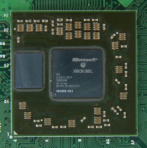
The Xbox 360’s eDRAM on the left and GPU on the right (image by ZyMOS from Wikimedia Commons, under the CC BY-SA 4.0 license)
.jpg)
Note that the Xbox 360’s eDRAM is not just raw memory accessible by the GPU. The separate chip, on the left of the picture, along with the memory itself, contains all the pixel output-merger logic. It’s connected to the GPU with a 32 GB/s interface. However, between the raster operation hardware and the memory, there’s a whopping 256 gigabytes per second of bandwidth!
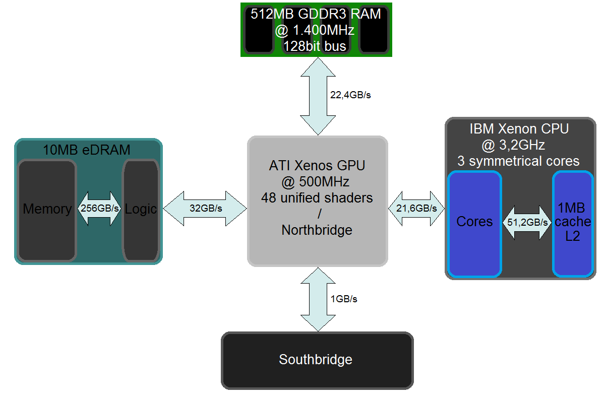
The Xbox 360 memory architecture (image by RiccardoTheBeAst from Wikimedia Commons, under the CC BY-SA 4.0 license)
This internal bandwidth is what made the Xbox 360 able to handle translucent surfaces and MSAA at no framebuffer memory bandwidth cost, even without compression techniques such as deduplication of color values and decoupling of them from sample coverage. Remember that we have 32 GB/s of bandwidth between pixel shading and the raster operations block, and 256 GB/s between raster operations and the pixel memory — 8 times more.
Suppose we got a color value from the pixel shader, and we want to write it to the frame buffer. In the simplest case, we need to just write that color to memory — 1 memory operation. But we’re rendering a translucent effect such as glass or smoke, thus we need to blend our color with what was drawn before — so we need to fetch the current color from the framebuffer, and we have 2 read/write operations now. Now, let’s add 4x multisample anti-aliasing to the equation. The concept behind MSAA is that while color values are stored separately for each of the samples within a pixel, in contrast with pure supersampling, the shader is still executed once for the whole pixel. So, we still have one value as the input, but we need to write to 4 locations in the framebuffer. And for translucency, we need to mix the color with what’s stored in each of them — so with 4x MSAA and blending, we get 4 reads and 4 writes, or 8 framebuffer memory operations per shader. This corresponds nicely to the 32 GB/s : 256 GB/s ratio of external and internal bandwidths of the eDRAM and raster operations chip — even the combination of 4x MSAA and blending is still as fast as writing a single opaque sample.
Note: The previous paragraph assumes that the source color (from the shader) has the same bit depth as the destination (the framebuffer) — usually 32-bit (8.8.8.8 normalized and 10.10.10.2 floating-point RGB + normalized alpha being the most common). It is generally okay to reduce the precision of the source value — which was calculated by the shader as a full 32.32.32.32 vector of floating-point point numbers — as the error is small enough not to cause any significant difference, especially considering it will be converted in the end anyway; the Direct3D 11.3 functional specification, which governs the behavior of present-day PC GPUs, also defines that “blending operations may be performed at equal or more (e.g up to float32) precision/range than the output format”. One exception from the “blending is free” rule, however, is alpha blending with 10.10.10.2 formats, where pre-conversion of the source alpha to 2 bits would leave only “completely invisible”, “33% visible”, “66% visible” and “fully opaque” options, which is unsuitable for practical usage for smoothly translucent surfaces. For this purpose, the Xbox 360 provides the 2_10_10_10_AS_10_10_10_10 and 2_10_10_10_FLOAT_AS_16_16_16_16 render target pseudo-formats, which cause the source alpha to be represented as 10-bit or 16-bit, but in this case, the whole RGBA color can’t fit in 32 bits anymore — thus will be using more of the bandwidth between the GPU and the eDRAM chip.
The final part of MSAA, resolving — averaging of sample color values to produce the final anti-aliased image and writing the result to the main GDDR3 RAM — is also done without bandwidth impact relative to copying a single-sampled image from eDRAM to the main RAM. Two or four samples are fetched and averaged by the eDRAM chip itself too over its internal 256 GB/s connection, and only the final, lightweight single-sampled image is sent to the GPU.
Dedicated bandwidth for framebuffers, along with free multisampling, has contributed heavily both to the crispness of many games at the console’s intended target 1280x720 resolution at 30 FPS or above. But let’s go back to the harsh reality of emulation, where we need to reproduce the way render targets are configured on the console, without all this beautiful and fast hardware architecture. Of course, all those bandwidth numbers have no use for that, and all that matters is doing what the game’s rendering logic expects the console to do — with correct handling of as many edge cases as possible. And this is where the most prominent clever optimization becomes the worst bottleneck.
The Xbox 360 allows games to draw only to eDRAM — after drawing, resolving (this term denotes both MSAA resolving — averaging — and simple copying on the console) is necessary to write the result to the back buffer for presentation or to a texture for subsequent usage in shaders. This matches the way rendering is done on tile-based GPUs — a region (“tile” or “bin”) of the scene is drawn, with depth testing, overdrawing surfaces, and possibly MSAA, to a small block of high-bandwidth memory (eDRAM or eSRAM), and the final result (if needed, with averaged MSAA samples) is then written to the corresponding portion of the texture in regular memory; and then this is done for another region, and another, until the entire image is completed.
On mobile GPUs, since those devices are battery-powered, tiling is done to maximize bandwidth with low energy use. The Qualcomm Adreno 200, which is based on the Xenos, only has a 32-bit interface for the main memory clocked at 166 MHz, providing 1.3 GB/s of bandwidth — 17 times smaller than on the Xbox 360. On-chip memory uses a lot of die space, however — so on Adreno 200, only 256 KB of tile memory is available, which is enough for just a 256x128 portion of the framebuffer with a 32bpp color buffer and a depth/stencil buffer without MSAA. This makes full tile-based rendering, with the “draw the first tile to all of the tile memory, resolve, draw the second tile overwriting all of the tile memory again, resolve, and so on” pattern being pretty much the only way of drawing a scene.
On the Xbox 360, however, there’s 10 megabytes of this memory. This is not enough for a full 1280x720 scene with MSAA — with 32 bits of color and 32 bits of depth/stencil data per pixel, 14 MB would be needed for 2x MSAA, and 28 MB for 4x — so HD games with MSAA used tile-based rendering too, albeit with much bigger tiles (1280x512 for 2x MSAA, or 1280x256 for 4x, in the above mentioned case, or smaller if multiple render targets are written). However, it’s enough for entire 1280x720 color and depth framebuffers without MSAA, or smaller render targets with 2x MSAA (such as 1024x600 in the Call of Duty: Modern Warfare series), or multiple smaller-sized render targets for whatever post-processing and composition the game wants to do. This gives games a lot of flexibility in management of framebuffers located in eDRAM, including control of lifetime of each eDRAM allocation and its purpose in each part of the frame.
The deferred lighting example provided in the beginning of this section would look like this on the Xbox 360 — differences from the PC highlighted in italics (using a framebuffer smaller than a full 3600 KB 1280x720 as an example, since three 1280x720 buffers can’t fit in the 10 MB of eDRAM):
- Create the device with a back buffer surface for final output.
- Create the normals texture.
- Create the diffuse/glossiness texture.
- Create the depth texture.
- When drawing a frame:
- Bind the eDRAM 0–3000 KB range as 10.10.10.2 render target 0.
- Bind the eDRAM 3000–6000 KB range as 8.8.8.8 render target 1.
- Bind the eDRAM 6000-9000 KB range as the depth render target.
- Draw the geometry to fill the G-buffers.
- Resolve the render target in the eDRAM 0–3000 KB range to the normals texture.
- Resolve the render target in the eDRAM 3000–6000 KB range to the diffuse/glossiness texture.
- Resolve the render target in the eDRAM 6000–9000 KB range to the depth texture.
- Bind the eDRAM 0–3000 KB range as 8.8.8.8 render target 0.
- Bind the normals texture to the pixel shaders.
- Bind the diffuse/glossiness texture to the pixel shaders.
- Bind the depth texture to the pixel shaders.
- Draw the lighting pass and things like UI.
- Resolve the render target in the eDRAM 0–3000 KB range to the back buffer surface.
- Present the back buffer to the screen.
See how now we draw first not to the textures directly, but to locations in eDRAM, and then we copy from it to textures in the main memory. And unlike on the PC, where each render target is located in a separate place, we’re now using the 0–3000 KB range of eDRAM for two purposes during the frame — first to write the normals, and then to shade and compose the final image.
In this usage pattern, the range is used for two entirely separate render targets just like on the PC. That’s what the old (Vulkan-based, but this is irrelevant as the differences are purely in the high-level emulation logic) GPU subsystem of Xenia was doing — to attempt managing eDRAM render targets in a way similar to how it’s done in PC graphics. There are no handles of separate render targets — like IDirect3DSurface9 objects, ID3D11Texture2D + ID3D11RenderTargetView pairs, OpenGL texture and framebuffer names — on hardware level in general, and even more prominently within the tight space of eDRAM designed for temporary use. So, the closest identifier to use was the properties of the render target — location in eDRAM, width (not height — it’s not required by the console and thus not specified directly in the registers, which is another significant issue), MSAA sample count and format. This was, of course, not the deliberate ultimate goal — there was actually a rough attempt to do the proper logic. Rather, it was a prototype implementation relatively quick to set up and to get a lot of games working to some extent, mainly cross-platform games not heavily utilizing Xbox 360-specific features — and it worked pretty fine in many cases, including the deferred lighting example above, more or less fulfilling the need for displaying the game world — sometimes enough for playing, sometimes at least just for observing how different parts of the emulator work.
But what if the game does something beyond “draw one pass, resolve, draw another pass, resolve” with eDRAM?
The game is in full control of what’s being stored in eDRAM and how render targets are placed in it. Thus, to draw a region of eDRAM, all it needs to specify is the address and render target parameters — width, MSAA sample count and format. But simply binding a framebuffer on the Xbox 360 only reconfigures the logic of pixel output — addressing and format packing. It will have no effect on the contents currently stored in the memory, until you actually draw anything after setting the new configuration. And among what this allows for is reinterpreting the data currently stored in eDRAM with a different format or layout. Some common examples of when it’s done are:
- Clearing render targets of any type to a single value. The Xbox 360’s GPU doesn’t have a special clear function — there is clearing logic in resolving, but it only clears alongside copying from eDRAM to the main RAM; otherwise the only way to clear is to a rectangle using regular drawing logic. Earlier we looked at how multisampling was free on the Xbox 360 — all sample replication is performed within the eDRAM chip and written to the memory at the internal 256 GB/s bandwidth, not the 32 GB/s between the GPU and the render target logic. For color (not for depth since polygon intersections need to be antialiased too — but depth is handled differently overall), MSAA replicates the same value into all the covered samples of the pixel — and we want to fill the whole render target with the same value, so why not use the MSAA logic to clear 2xAA render targets twice as fast, and single-sampled render targets 4 times faster? Xbox 360’s 2xAA render targets samples are internally stored like 1x2 single-sample pixels, and 4xAA samples map to 2x2 pixels without MSAA. Thus, to clear a 1280x720 single-sampled render target, games (more specifically, the Direct3D 9-like graphics library that, unlike on the PC, is a part of the game executable itself, so from our perspective it’s just game code that is directly interacting with the console’s hardware) can draw a 640x360 rectangle with 4x MSAA at the same location in eDRAM where the 1-sample 1280x720 would be. But the Xbox 360 graphics library does not stop at this. To draw to a color render target, the pixel shader needs to be executed for every pixel covered, and the resulting value then needs to be copied via the 32 GB/s interface between the GPU and the eDRAM chip. But we need to write the same value to all pixels — so it’s wasteful to run the pixel shader all the time if it returns the same value. What doesn’t need per-pixel data, however, is depth — for the whole triangle (of the size of half of the screen), all the information needed to calculate depth in any place in it is 24 bytes — Z and W coordinates of its three vertices. Since the framebuffer needs to be cleared to a constant value, the most optimal way on the Xbox 360 to clear a framebuffer is to draw a rectangle parallel to the “view” (with constant Z and W coordinates) to a 4x MSAA depth render target in the same location in eDRAM — with the low 8 bits of the needed packed 32-bit value written via stencil, and the upper 24 bits converted to floating-point and divided by 0xFFFFFF to become the “depth” of the rectangle to draw.
- Reuploading a depth/stencil buffer to eDRAM. Sometimes the game may draw something involving depth/stencil in multiple passes in different parts of the frame, but in between they may draw something else using eDRAM — and with the depth/stencil buffer, there may be not enough eDRAM for those passes in the middle, so they may temporarily evict the depth buffer by resolving it to the main memory, and then to reload it to eDRAM when it’s needed again. Among the use cases for this behavior are things like 3D UI markers that may need to be hidden if they’re behind walls, but shouldn’t accept lighting, tone mapping or other kinds of postprocessing. Especially this happens when the game uses MSAA and thus tile-based rendering, such as the main menu and the intro cutscene of Halo 3 — there is not even enough memory to draw all of the image in one go, so if the game needs to use the depth/stencil buffer after the tiled pass, it surely has to dump every tile of it to the RAM and then load it back. For this, the game binds a color render target at the same location as the destination depth buffer, and then writes the depth/stencil image as color. Even though the Xbox 360 has pixel shader depth override output, the reason why a color render target is needed is to upload both depth and stencil data — even to this day on many GPUs (Nvidia; and this does also cause inconvenience in the new render target cache of Xenia), stencil reference value can only be set for the whole draw call, not for each pixel individually, so a 8.8.8.8 render target is used, with the 8 stencil bits written as the red channel, and the 24 depth bits as green, blue and alpha.
With the PC-like approach, treating all render targets as separate would mean that something as basic as clearing the framebuffer — importantly the depth buffer, otherwise even if the player moves backwards just a little, the game won’t be able to draw the scene anymore — won’t even work. So, sharing eDRAM contents between PC render targets is absolutely necessary.
Now, if you have seen the modern GPU APIs like Direct3D 12, Vulkan and Metal, you may be wondering: we’ve been discussing PC framebuffers being completely separate from each other in terms of older APIs like Direct3D 9 or 11 and OpenGL, but what about the new ones where you can place resources manually at specified locations in an ID3D12Heap, VkDeviceMemory or MTLHeap object? Can their aliasing mechanic be the solution?
The answer is no, and it was never their job to be one. The reason is that on the PC, there is a broad variety of different GPU microarchitectures from various vendors, and the purpose of a PC graphics API — no matter whether it’s a “stateful” API with internal resource tracking like Direct3D 11, or a more “bindless”-oriented one such as Direct3D 12 — is to provide a unified way of programming them all. Images in general, and framebuffers in particular, are stored in a swizzled way internally in graphics memory. If an image is stored in a linear way — all the data of the first row, then the second row, and so on — pixels adjacent along the X axis are stored near each other, but along the vertical axis, adjacent rows are located sparsely, which is cache-inefficient — textures may be rotated on the screen any way, and they need to be filtering along both directions, and framebuffer access patterns also must more or less agree with the way textures are accessed. Each GPU microarchitecture has its own data layout that is optimal for that specific architecture. AMD GCN represents images as 8x8 “micro-tiles” (not to be confused with tile-based rendering) arranged in some macro-tiling order, Nvidia GPUs have their own concept of “groups of bytes” in blocks. In addition, GPUs may have additional lossless compression structures for framebuffers, used to reduce bandwidth — such as hierarchical depth buffer storing depth boundaries in a region and a more compact depth representation (such as original polygon plane equations) for rejection of many pixels at once, various forms of delta color compression, fast clearing masks, MSAA sample value deduplication structures. These are implementation details which not only vary across vendors, but also may be changed between GPU generations as the hardware involved is improved, and more optimal access patterns themselves are found. So, a PC graphics API has to abstract away those differences to provide a unified, predictable interface that would be compatible with the diverse set of current and future hardware.
The Xbox 360’s GPU also has its own optimal data layouts — but it’s a gaming console with a fixed hardware configuration, so details of the actual data arrangement are known to game developers, and they can take advantage of direct data access to make their algorithms work better on the Xbox 360. Framebuffers in eDRAM are no exception. eDRAM is split into “tiles” — mostly no relation to tiles in tile-based rendering (just a generic term for something aligned to a regular grid), the Xbox 360 refers to multiple concepts as “tiles”, but here it’s the granularity of addresses and of row offsets of render targets) — at 32 bits per sample, of 80x16 MSAA samples per tile, which corresponds to 80x16 pixels without MSAA, 80x8 pixels with 2x MSAA, and 40x8 with 4x MSAA. In addition, depth is stored differently than color — even and odd vertical columns of 40 samples within each tile are flipped in depth buffers as opposed to color buffers — and this flipping is explicitly done in game shaders when they need to reupload depth after evicting it from eDRAM. 64bpp formats also have their defined layout — we’re hoping to find a game where they’re reinterpreted to or from 32bpp for some purpose…
Why the old GPU emulation implementation happens to display the normals G-buffer to the final output is because of a few unhandled cases in the framebuffer data flow. Here’s what happens to the normals buffer during a Halo 3 frame:
- The game writes the normals to an integer 10.10.10.2 render target in eDRAM.
- The eDRAM 10.10.10.2 render target with normals is copied to a texture that is later used in the lighting pass.
- Various frame passes are drawn to different render targets.
- The shaded image of the game with bloom, and then the HUD elements, are drawn into a floating-point 10.10.10.2 render target that happens to be in the same eDRAM range as the integer 10.10.10.2.
- One limitation of the Xbox 360’s GPU is that the 10.10.10.2 floating-point render target format is only available for render targets — not textures that can be read after exporting from eDRAM to the main RAM. The composition and HUD passes write the colors in such a way that they can be passed to the screen as an 10.10.10.2 integer image. So, after drawing the HUD, Halo 3 copies a 10.10.10.2 integer render target (overlapping the location with the 10.10.10.2 floating-point image) to a 10.10.10.2 integer texture and sends it to the screen.
As we can see, the final image data, with the shaded game scene and the HUD, should come from the 10.10.10.2 integer render target. However, it was written to the same eDRAM location as floating-point — but since there was no sharing of eDRAM contents, the old render target cache was simply looking up the last Vulkan framebuffer image that was used for drawing as 10.10.10.2 integer — and it happens to be the normals G-buffer, so it ends up on the screen.
Back before the development of the new Direct3D 12-based graphics backend began, an attempt was made to add full-blown eDRAM contents sharing between Vulkan framebuffer images. It was hoped that it would get Halo 3 rendering to work, however, it had hit another architectural roadblock.
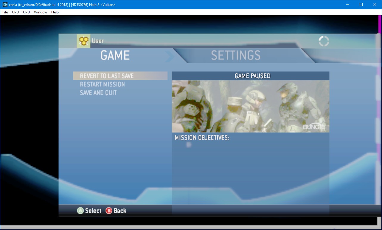
Early eDRAM data sharing experiment — for those who have completed LASO, the Blind skull in reverse (Halo 3, by Bungie)
As you can see, now we have a situation somewhat opposite to what we started with. The reinterpretation of data between 10.10.10.2 floating-point and 10.10.10.2 integer now works. But now we can’t see the world.
This time, it’s an issue related to storage of main RAM textures. They also have their own storage layout — 2D textures are stored as a sequence with 32x32-pixel (or 32x32-block, for compressed textures) tiles with a micro-tiling addressing function, and 3D textures have 32x32x4 tiles (though addressing is repeated every 32x32x8 pixels). Copying from eDRAM to the main RAM also writes pixels in this layout.
The old graphics code handled this layout when loading textures on the CPU, to convert them to a layout uploadable to Direct3D 12 textures. However, render-to-texture happens within the GPU (except for some CPU readback cases). So, the previous Xenia GPU emulation implementation handled render-to-texture results separately from regular textures loaded from the console’s unified memory on the CPU. Regular textures were loaded from the console memory, and converted from the 32x32-tiled layout. However, render-to-texture instead had a separate cache, and when the emulator wanted to load a texture, it would first search in that cache whether anything was copied from eDRAM by various properties of the texture — such as address (with certain heuristics to handle some cases of tile-based rendering, which involves copying each part to the an area in the middle of the target texture rather than to its entirety), format, width, height. And if a matching render-to-texture cache entry was found, it would be used instead of the data from the unified memory.
32x32-tiled layout means that textures (assuming no mips) of sizes, let’s say, 33x33, 63x33, 64x33, 64x64, are stored the same way in memory — if their size isn’t a multiple of 32x32, the texture is simply padded to 32x32 tiles with unused bytes. So, to calculate an address in the texture, you don’t need its exact size in pixels. You only need to know the number of tiles along the horizontal axis to get how distant rows of 32x32 tiles are from each other in memory — the row “pitch” or “stride”.
During eDRAM > RAM copying, the console’s graphics library specifies the dimensions of the destination texture for address calculation purposes. The height passed to the GPU is, surprisingly, specified exactly in pixels (even though it’s not even needed for copying to 2D textures, only for the rare cases of rendering to a 3D texture). But the width, or, more specifically, the pitch, is rounded to a tile — to 32.
Halo 3’s bloom effect performs multiple passes of resizing an image containing bright parts of the scene while blurring them — each of them involving drawing the downsized and blurred image to eDRAM, and then copying it to a texture. And one of the passes creates a 72x40 image. But as we mentioned, in render-to-texture, the GPU receives the width rounded to tiles. So Xenia sees that the game wants to copy an eDRAM region to a 96x40 texture. And the old GPU subsystem created a 96x40 texture in the render-to-texture cache.
But reading from a texture requires its exact size — for correct scaling, repeating or clamping of coordinates. And the game later wants specifically a 72x40 texture. But since the image was copied to a 96x40 texture instead, Xenia can’t locate the needed 72x40 texture in the render-to-texture cache, and falls back to load it from the CPU-side memory — where it, of course, was never filled, and loads just zeros instead. Halo 3’s bloom shader, however, is done in such a way that areas with 0 in the alpha channel become black in the end — and since the entire bloom texture has an alpha of 0, the end result was also completely black.
That’s when it was decided that something completely different was needed.
We need to go lower-level
With all the architectural issues, major changes were needed. While eDRAM logic is pretty localized within the render target cache, the changes to texture loading would have much more far-reaching effects.
What’s more effective than fixing the symptoms of an issue is fixing its root cause. Instead of trying to handle more and more edge cases, what would be much more straightforward is to do what the console does, and instantly cover all the eDRAM > RAM copying cases, and all the subsequent texture loads — actually write the data in the Xbox 360’s texture layout with the original addressing and format. Not only would mismatching texture width and copy pitch and all tiled rendering — both vertical and horizontal — where the final texture is constructed from multiple copy operations to different locations with the textures “just work”, but also, for instance, reinterpretation of texture data in a different format — such as reading copied 24.8 depth/stencil as 8.8.8.8 color for depth/stencil buffer reuploading.
This requires handling the Xbox 360’s 32x32-tiled texture layout on the GPU, where rendering to textures is performed — the tiled address needs to be calculated on the GPU in both eDRAM > RAM copying and texture loading. That was done on the CPU for regular texture loading in the previous implementation — but since on the real console, addressing is the same for both textures from game assets and from eDRAM resolves (it doesn’t distinguish between them in any way), why handle them separately on Xenia, and convert textures to the layout accepted by Direct3D 12 on the CPU at all? So it was decided to handle texture memory on the GPU in a unified way, preserving the way they are stored on the real console in host GPU memory.
But if we can use the addresses provided by the game on the host GPU, why not use them for everything referencing the console memory on the GPU — vertex buffers, index buffers, exporting to the console memory from shaders (another unique feature of the Xbox 360 — something between ATI’s “render to vertex buffer” and Direct3D 10 compute shader functionality that appeared later)?
With render target handling requiring major modifications, and a complete switch of the approach to emulation of everything that touches the memory on the GPU, the amount of things to rewrite basically became bigger than we could keep. So, for faster iteration without old architectural constraints, it was chosen to do the experimenting in a completely separate GPU emulation backend restarted from scratch.
That’s how in the summer of 2018, work began on the current Direct3D 12-based GPU subsystem implementation. To clarify, there were no technical limitations that would prevent the emulator from using Vulkan instead, just like previously — and a new Vulkan-based GPU backend is currently in development based on the architecture of the current backend (that’s part of the reason why the render target cache update was created — the 2018 render target logic was very experimental and prototype-like, had performance and architecture/code quality far from satisfying, and there was no will to continue evolving or to port it. Direct3D 12 was chosen as it was extremely quick to set up — there was no need to write hundreds of lines of code, to handle the possibility of the presentation queue being the same or different, and to handle all the details of the OS’s presentation system, only to set up the window, for example. In addition, the developer of the new backend (me) was already familiar with the concepts of the Direct3D 12 API and its usage practices. This decision, however, had an unexpected positive consequence some months after the early “stable” versions of the new GPU subsystem were released — which we will discuss later :)
The core part of the current Xenia’s GPU implementation is the “shadow copy” of the console’s physical memory on the host GPU side. The unified RAM of the console is represented as a 512 MB buffer in Direct3D 12. Even though modern graphics cards have many gigabytes of RAM, still, to slightly reduce the memory usage of that buffer, it’s not allocated in its entirely from the beginning — rather, using the “tiled resources” feature of Direct3D 12 where supported (on almost all Direct3D 12-compatible GPUs), smaller portions of the buffer are allocated on demand.
The Xbox 360’s memory is unified between the GPU and the CPU — both can access the same memory without any penalty. But most gaming PC setups have discrete graphics cards with their own dedicated RAM that is accessible much faster within the GPU than the CPU memory which needs to be fetched via PCI Express. Also, Xenia’s GPU command processing adds one more layer of asynchrony between the drawing commands and the real GPU hardware.
On the real console, the GPU command processor runs on the GPU, in its work timeline. For instance, if the game inserts a synchronization event, like, to wait for the completion of some draw command — referencing a memory region to be able to overwrite that memory region — on the real console, such an event will be signaled when the object specified by the draw command has actually been drawn. And not only that specific draw call — all the submitted work preceding it, which may be worth many milliseconds, will be completed by the time the GPU command processor reaches that event.
Xenia’s situation is different. The console’s GPU command processor is implemented on the CPU instead — because all the resource setup, all shader translation and graphics pipeline state management, has to be done on the CPU. And Xenia doesn’t submit every single work immediately to the GPU. Rather, it builds Direct3D 12 command lists (by processing game-provided command lists…) and submits them at the end of the frame. But more importantly, it doesn’t await completion of the work in the current frame. Now, awaiting is definitely required for cases of GPU-to-CPU readback — even though it’s necessary for a lot of things, like eye adaptation to scene brightness in HDR code in many games (which is why games on Xenia are often overly bright or dark), screenshots in game saves — it’s currently only implemented in a hacky way due to not yet well-researched issues encountered when an attempt to add it was made. But if you enable the d3d12_readback_resolve configuration option, you can see the biggest problem with mid-frame synchronization involving waiting right after submitting — it makes the host GPU run in lock-step with the CPU rather than in parallel. If you’re spending 16ms on the CPU to prepare 16ms of GPU work, and just “firing and forgetting”, you will be able to render new frames every 16ms — you spend 16ms to generate the commands on the CPU, submit them to the GPU, and immediately move on to the next frame. While the CPU is preparing submission N+1, the GPU is drawing submission N. If you wait for the completion right after submitting the command list, the CPU will spend 16ms preparing the frame, submit it to the GPU, and then wait 16ms before going to the next frame — so it will only be possible to render frames every 32ms, with either the CPU or the GPU doing nothing for a long time. So the GPU shadow copy of the memory also needs to be updated asynchronously — placing new data in a temporary buffer on the CPU, and copying from that buffer to the actual shadow copy at the specific moments between draws in the host GPU timeline.
Because on the Xbox 360, resources are still bound through slots holding “fetch constants” (descriptors containing information about the bound textures and buffers), it’s possible to predict what memory is going to be needed by each draw call on the CPU, without running the shader (with the exception of the shader memory export functionality using shader output registers rather than fetch constant slots for configuration — but thankfully, pretty much all games that use memory export set up that output register the same way, and that still lets us grab the offset and the size of the buffer from the known general-purpose constant register).
So, when the game wants to draw something, we’re checking whether the memory range backing each vertex buffer, the index buffer, and (for the initial nearby contents, as we can only validate/invalidate at the system page size — 4 KB — granularity) each shader memory export buffer, has all pages up to date in the shadow copy, and for the pages that have been modified or are being used for the first time, uploading the new contents from the CPU-side memory, and placing an access callback on them — marking them as “non-writable”, and each attempt to write to them made by the game code will trigger our custom access violation handler.
Unlike in the old Xenia’s GPU emulation implementation, there’s no concept of “buffer cache” for vertex and index buffers — the 512 MB buffer is bound directly as an index buffer, and shaders also fetch vertex data directly from it. Thankfully, the amount of RAM on the Xbox 360 is 512 MB — which nicely corresponds to PC graphics limitations for buffer sizes accessible by shaders. On Nvidia, buffers of up to 128 × 220 elements — and with 32 bits per element (since vertex data uses formats with sizes that are multiples of 32 bits), this is exactly 512 MB. The core Vulkan specification also requires that at least 4 storage buffers of 128 MB or more can be bound to shaders — so even in the worst case, all 512 MB can be bound to shaders. So, translated shaders can access vertex data from any location in the console’s memory (to be more precisely, the shadow copy of it) and export data to any place in it.
For textures, the same validation and uploading logic is used, but unlike vertex buffers, they are not read by shaders directly from the shadow copy — rather, a cache of Direct3D 12 textures is used, but this time textures are not uploaded from CPU-side memory directly. Instead, they are converted into Direct3D 12 textures from the data in the original console texture layout in the shadow copy — which contains data from both the CPU-side memory and render-to-texture — using compute shaders performing the tiled address calculation and, if needed, pixel format conversion (to load textures in Xbox 360-specific formats not supported on the PC), when a memory location is first used as a texture of the specified format and layout, or a previously used texture has pages in the memory backing it invalidated. This way, there are no issues like the one that was happening in Halo 3 with its 72x40 bloom texture being copied from eDRAM as 96x40 by design, as the texture cache doesn’t distinguish between textures from the CPU-visible memory and render-to-texture (with resolution scaling being the only exception), and the difference between the two has any importance only on the memory shadow copy level — pages can be marked as valid from either the CPU or the GPU, but the CPU (since Xenia doesn’t have readback yet — but with readback, GPU-modified pages will need even more complex handling) doesn’t know what the GPU has written to the pages that it has touched, so for them, invalidation needs to be done with more caution.
As invalidation relies on an access violation exception handler, and thus on memory protection on the host, the smallest region that a callback can be enabled for is 4 KB. When the game code writes to a location in a GPU-visible memory area that was previously actually accessed by the GPU (and thus uploaded to the shadow copy), the respective 4 KB portion of the shadow copy is invalidated, along with textures backed by a memory range that includes that page. But since triggering an access violation handler is a slow operation, requiring multiple switches between the user space and the kernel space, mutex locking, and lookups in the GPU emulation code, and it may happen many times in a tight loop like the memcpy function in the game if it’s copying a large amount of data, invalidating only 4 KB at once may cause noticeable slowdown — the original Doom, which is software-rendered, ran at roughly 3 FPS on the developer’s desktop PC with the naïve per-page invalidation. Instead, Xenia invalidates a bigger region around the touched location — 256 KB was chosen as an optimal tradeoff — but the range being invalidated may actually be smaller if render-to-texture or shader memory export results are placed nearby — as while it’s safe to upload the same CPU-side memory contents multiple times, GPU-generated data is not mirrored in CPU-visible memory in Xenia, so it must be invalidated as precisely as possible (thankfully, textures on the Xbox 360 must be aligned to 4 KB, which maps nicely to the page size on Windows and common Linux setups).
That’s how unified GPU and CPU memory is emulated in Xenia, but let’s talk about the more interesting part — the render target cache!
The idea of the render target cache was roughly the same — to use a buffer where data is stored in the same format as on the console, but now, rather than for the unified memory, it’s for the 10 megabytes of eDRAM. But as we discussed previously in the section about the old GPU subsystem implementation, Direct3D 12 render targets have opaque storage, and we can’t just create arbitrary views directly into that 10 MB buffer.
So, it was decided to use Direct3D 12 render targets as transient views. From the eDRAM buffer, data would be loaded to host render targets — indexed simply by width and format, plus additional index to be able to bind multiple render targets of the same format at once — when those render targets become active. And once the game needs a different set of render targets, the contents of the previously bound ones are flushed to the eDRAM buffer.
A prototype implementation was quickly made, roughly the same as what was used in the initial tests before the beginning of the Direct3D 12-based graphics backend. Whenever any change happened in the render target bindings, all data from the last used ones was stored, and then all the data was loaded into the new render targets.
One issue with this approach that appeared early was that the concept of a “binding change” on the hardware level is not the same as just a call to a function like OMSetRenderTargets in a graphics API. We don’t know when the game actually deliberately unbinds a render target — the hardware registers containing the current render target info simply do not have to be modified for the slots that new render targets are not being bound to if the game is not planning to actually write to them, as they will have no effect. So if the game was first using a depth buffer located at the 0 KB offset in eDRAM and a color buffer at 3600 KB, and then binds only a color render target at 0 KB, we end up with both color and depth render targets using the same eDRAM range in their setup registers — which would make no sense as the two would be conflicting with each other. But in the color-only case, the game wouldn’t be using depth/stencil testing or writing, so the depth buffer will not be accessed, and thus the depth buffer configuration register will be completely ignored by the hardware.
So we need to check which render targets will potentially be used. For depth/stencil buffers, depth or stencil testing needs to be enabled. For color render targets, the color write mask value for the render target slot needs to be non-zero, and the current pixel shader should be writing to that render target. However, all this state can be changed many times during one rendering pass — some parts of the UI without depth testing can be drawn while rendering the game world, some objects may be written only to, for example, the render target in slot 0, but not to the one in slot 1. That’s what was happening in Banjo-Kazooie (the original one, not Nuts & Bolts) — just like in the Doom’s memory shadow copy invalidation case, just one operation caused it to become one of the slowest-running games on Xenia, at a framerate well below what can be considered playable. The game often interleaves depth-only drawing with draw calls with both color and depth used. The naïve implementation was performing the full store/load cycle whenever drawing to the color render target was enabled or disabled — and that was happening a lot of times during the frame. Later, a dirty workaround was added to handle specifically the case of disabling and re-enabling render targets, and not performing stores and loads, unless the newly bound render target overlaps another that was bound and disabled previously.
Overlap detection is also complicated for one reason — there are some cases when we don’t know the height of the region being drawn to. This may seem very strange, as on the PC you usually have to specify the exact render target size, the viewport, and possibly the scissor rectangle. But the Xbox 360 allows drawing without any of that — if you know the extents of what you’re going to draw in advance, and that you won’t draw more than you actually need (and touch other currently used eDRAM regions), you can skip all of that, and even return coordinates directly in pixels from the vertex shader. All that’s required is the width of the surface — to know where each row should go. That’s how screen-space rectangles are often drawn — including all clears performed by the console’s graphics library, and sometimes screen-space post-processing passes effects in games. And the height is not even passed when drawing regular world geometry, as it’s not needed for any calculations (it’s baked into the scissor rectangle when the viewport exceeds the render target size, for instance). For regular draws, we can estimate the maximum Y coordinate where any pixels will be touched — and thus the portion of eDRAM affected by the draw — on the CPU, from the viewport and the scissor rectangle. But for the draws without viewport clipping and scissoring, we can’t know the height touched until we actually run the vertex shader — which is executed on the GPU, not the CPU, so we have to approximate conservatively, being prepared for any polygons drawn by the game — from the amount of eDRAM remaining from the beginning of the render target, the absolute height limit of 8192 (which only actually matters for really narrow render targets anyway), and if multiple render targets are bound, the distance between the ones closest to each other in eDRAM. The worst case, however, is when there’s only one render target bound that is located in the beginning of eDRAM (which is very common, as this happens whenever it’s cleared). In this case, the entire eDRAM will be considered modified — and this is still a major issue even in the updated render target cache, as a lot of expensive copying happens with zero efficiency, doing wasteful round trips. This is something to investigate in the future — possibly fixable by creating a CPU-side shader interpreter and computing the boundaries from the positions the shader actually returns.
Among the consequences of possible round trips — and the need for accurate emulation overall — is the requirement that copying between render targets should preserve the exact bit representation of the data in the Xbox 360’s format while copying between PC render targets of different formats. And again, we have to deal with the fact that the Xbox 360 is anything but a PC — it has lots of custom render target formats that are completely unavailable on the PC! The Xbox 360’s GPU was clearly an experimental site that was well ahead of its time — it featured many features that were later added to Direct3D 10 and 11 on the PC, but they were implemented in significantly different ways. Among the color formats are:
- 10.10.10.2 floating-point, with 7 bits of mantissa and 3 bits of exponent (7e3) per channel, ranging from 0 to 31.875. This format was designed for HDR usage, for writing light values in a wider range, while using only 32 bits per pixel — two times smaller than the full 16.16.16.16 floating-point format. However, possibly because of small usefulness of a 2-bit alpha, and to support a much wider range of luminance, on the PC, 11.11.10 (6e5 red and green, 5e5 blue) became the industry standard instead. Xenia has to emulate it using 16.16.16.16 — it has a wider range, different precision, and alpha is encoded completely differently, but usually games use this format as a regular HDR color format without relying on edge case behavior, so it works mostly fine, even if it gets converted to and from 10.10.10.2 during copying round trips.
- 16.16 and 16.16.16.16 fixed-point — but unlike the usual PC 16_16_SNORM format, these ones have a -32 to 32 range rather than -1 to 1. We don’t know why such a decision was made, but it’s possible that the intention was to create a general-purpose format for both fractional and some integer values. In Halo 3, for instance, it’s used for distortion offsets for effects such as hot air behind the Ghost and the “lens” in the Forge mode. This format can be represented bit-exactly, by dividing the shader’s output by 32, however, blending, which is fixed-function and outside our control, will be broken — while additive blending will still work, multiplicative will behave a completely different way: as an example, 1 × 1 = 1, but if the values are divided by 32, it becomes 1/32 × 1/32 = 1/1024.
- 8.8.8.8 with the infamous piecewise linear gamma — we’ll talk about it later as the update adds a new path for emulating it, but the Xbox 360 performs blending in linear color space — so it will be incorrect if the conversion to the gamma space is done on pixel shader output.
The more interesting issue is the 24-bit floating-point depth with 20 bits of mantissa and 4 bits of exponent, ranging from 0 to 1.999… — this one almost could be available on the PC as well, and it’s present in PC Direct3D 9, but as an optional format only implemented on some old ATI graphics cards and the reference software renderer, and, very sadly, was completely abandoned later and didn’t make it into Direct3D 10. Floating-point depth buffer representation, combined with the “reversed depth” trick where 1 is considered “near” and 0 is “far” (as floating-point numbers don’t lose mantissa precision as they approach 0, which is totally not the case for approaching 1), is used to maintain a stable precision along a wide range of values, compensating for the hyperbolic nature of the Z value — allowing for large open worlds without significant Z fighting in the distance. The advantages of a floating-point representation are covered in Nathan Reed’s “Depth Precision Visualized” article.
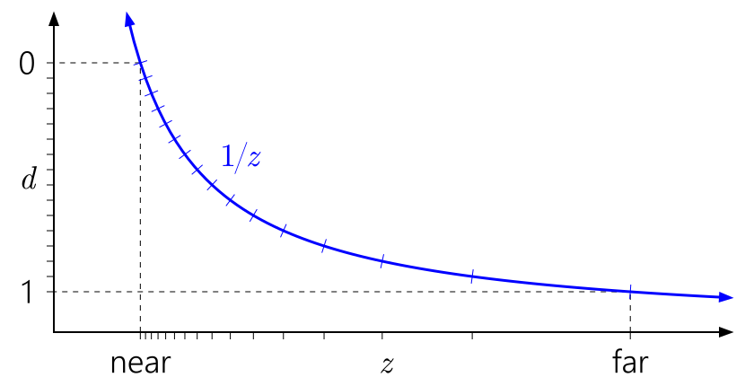
Integer depth precision distribution — notice the actual depth difference between adjacent depth buffer values becoming bigger and bigger as the distance increases
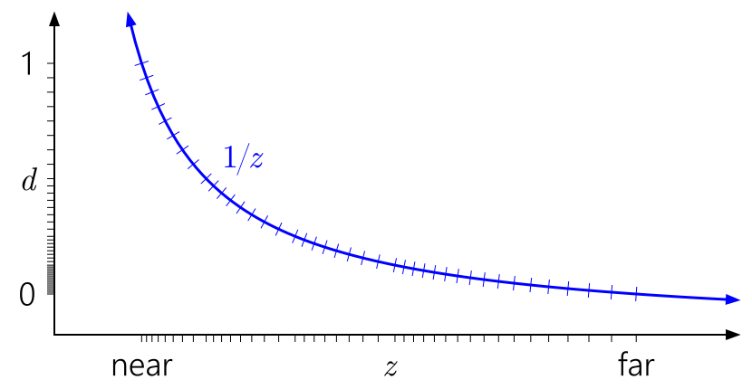
Floating-point depth precision distribution — as the distance increases, the precision stays stable (images by Nathan Reed from the “Depth Precision Visualized” personal blog post, under the CC BY 4.0 license)
And as this format is not available on the PC, we have to choose the closest alternative that is not worse than the original format — which, on the PC, is 32-bit floating-point. But since it’s a depth buffer format, it is largely outside our control if we decide to take advantage of the host GPU’s internal depth testing optimizations such as early and hierarchical depth rejection.
But we have eDRAM contents reinterpretation to consider here. The game only gives us 24 bits to put the depth value in — we can’t fit a 32-bit value in there. And the console’s 24-bit pattern needs to be interpretable as color, and — for reuploading depth from the main RAM to eDRAM — back. And as we can’t know the height affected by certain commonly occurring draws, and often “take over” the depth buffer with a color render target while clearing a color buffer preceding it in eDRAM — so the depth buffer must survive round trips. And what needs to survive is not only the 24-bit value “seen” by the game — it’s the host 32-bit value as well!
We can’t simply neglect the excess bits like we do with the 10-bit floating-point colors — as that would result in highly noticeable corruptions. The worst consequence is that the game will not be able to draw the same geometry twice after a round trip. Multipass rendering requires the depth to be exactly the same as the one that is already stored in the depth buffer — otherwise a wall drawn twice will not be the same wall anymore. Such a conversion would drop 3 bits of mantissa and a huge portion of exponent ranges — and as a result, only roughly 50% of pixels will pass the depth test if the game uses the “closer or equals to” comparison in the second pass, or 12.5% if it uses “equals to”. And multipass rendering is extremely common on the Xbox 360 — the most prominent example is using a Z pre-pass to take advantage of Xbox 360’s fast hierarchical depth buffering not to run the pixel shaders for surfaces hidden behind other geometry.
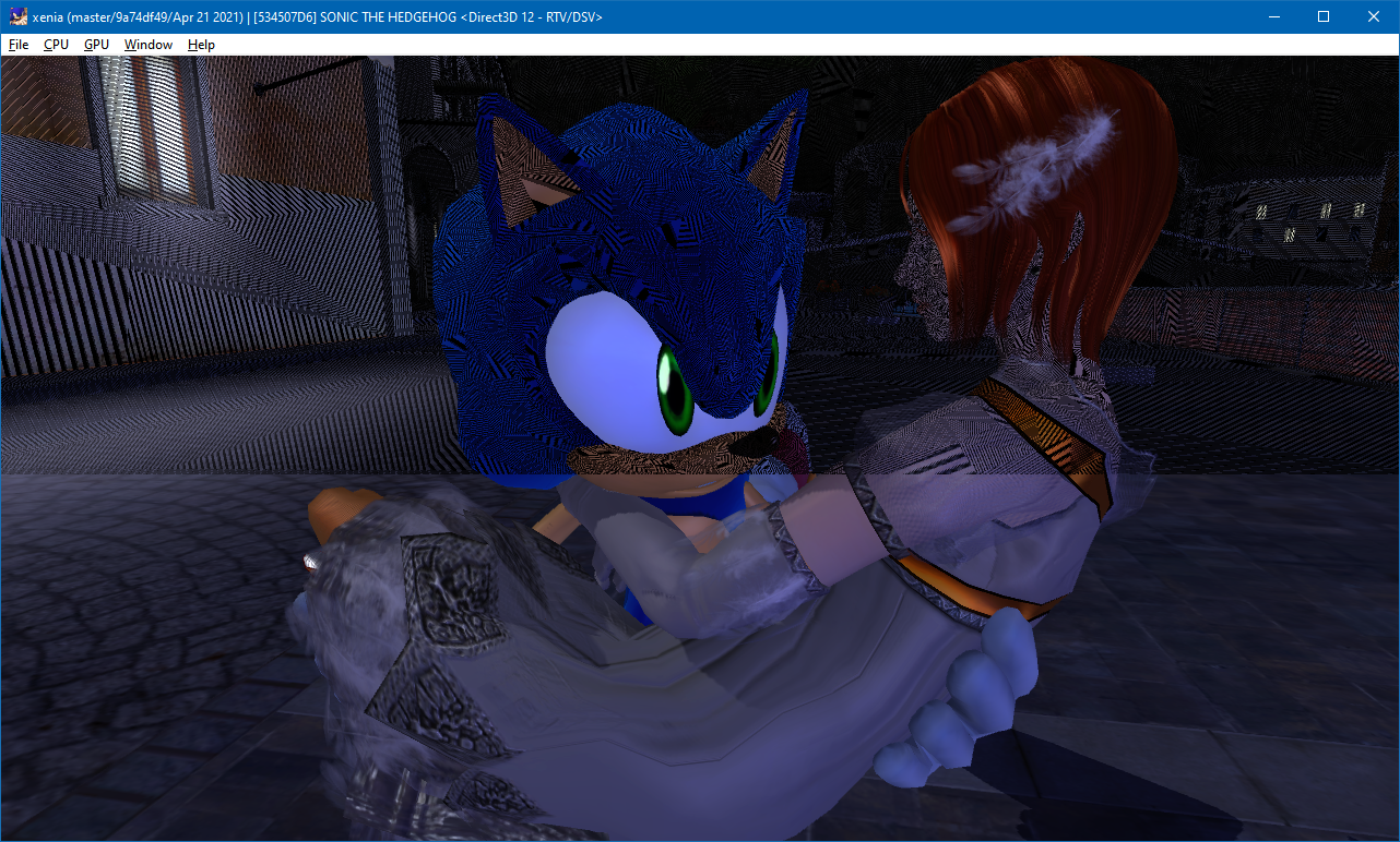
A example of what happens if the 32-bit representation of the depth buffer is not preserved — the game uses a depth pre-pass and a color pass, and the dark areas are where the depth test in the color pass has failed (Sonic the Hedgehog, by Sonic Team and Sega)
But we still need to be able to invalidate the host 32-bit depth in case it was actually modified through a different format — the most common case of this is clearing, with a 24-bit integer depth buffer with 4x MSAA, another instance is reuploading — and use the new value instead.
The solution is to maintain eDRAM contents in two formats — the original console format and the host 32-bit format — and to check whether the 32-bit depth data is still up to date. So, the eDRAM buffer is now sized not 10, but 20 MB — one half containing the color or depth/stencil value for each sample, and another storing the 32-bit floating-point depth values. When a color buffer (or a 24-bit integer depth buffer, which is used for clearing, and is natively supported on Direct3D 12) is stored to the eDRAM buffer, the data from is written only to the original format half. But when a 24-bit floating-point depth buffer, that is emulated as 32-bit, is stored, the value that goes to the first half is the 32-bit depth lossily converted to 24-bit, but the second half receives the unmodified 32-bit value. And when it’s time to load it back, if the new data is needed as color or as integer depth, it’s read as 24-bit as normal, but if it’s loaded to a 32-bit depth buffer again, the up-to-date check happens — the currently stored 32-bit depth is converted to 24-bit, and if it turns out to be the same as the stored the 24-bit value, then the full-precision 32-bit value is loaded — otherwise the stored 24-bit value is converted.
This works fine for clearing, however, it doesn’t help with reuploading the depth buffer after it’s evicted from eDRAM, except for a small part of such cases (when it’s reuploaded to the same location where it was prior to eviction, and its region was not used to hold a different floating-point depth buffer) — once the depth buffer is exported to a texture in the console’s memory, it’s converted to 24-bit, written to the unified memory, and the track of such memory is lost. And when it’s reuploaded back, the full 32-bit depth is not available anymore — so loading has to convert the lower-precision value. Some effects, such as light bounding volumes in deferred lighting, still mostly work, but the game can’t do multipass rendering with that depth buffer anymore — some precision is lost already, and the same issue as we discussed above happens.
Later, a special path was added for using 24-bit floating-point depth directly, solving the reuploading issue — the depth_float24_conversion configuration option — without a separate eDRAM view for 32-bit depth, by converting the depth value on pixel shader output. However, this accuracy improvement comes at a severe performance cost, and thus this option is disabled by default:
- Internal depth optimization on the host GPU, such as representing regions of the depth buffer as polygon plane equations, don’t work anymore, as Xenia is writing arbitrary depth values that can’t be reconstructed using the GPU’s depth compression algorithms anymore.
- Early depth testing possibilities are severely limited. There’s no way for the GPU to both perform depth testing and writing at once before running the pixel shader, as the pixel shader needs to be executed for the GPU to know the depth value. Moreover, early depth testing can even be disabled at all depending on how the conversion is done:
- Truncating conversion option keeps the possibility of performing the depth test slightly coarsely early by using conservative depth output (SV_DepthGreaterEqual instead of SV_Depth). In this mode, conversion is done in such a way that the converted value can be only considered “farther” (closer to 0 — which corresponds to the far clipping plane with the reversed depth range commonly used on the Xbox 360) — if pixels of a polygon were rejected early because they were behind a wall, the conversion can’t put them in front of the wall, rather, it can only push them only deeper. This, however, results in rounding being incorrect (at least according to the Direct3D 9 reference implementation — may be untrue actually, at least according to how format conversion works according to the Direct3D 11 specification, we still need to investigate…), but that mostly doesn’t have any noticeable effects.
- Rounding conversion can round in both directions (specifically, to the nearest even), but this results in conservative depth testing being unusable, and completely disables early depth testing — and all the pixel shading, which may include lighting or other expensive effects, has to be performed even if the pixel is behind a wall.
- With MSAA, unlike color, depth is calculated separately for every sample — otherwise anti-aliasing could only work on polygon edges, but not on geometry intersections. But in order to convert the depth value, we need to know it in the pixel shader — but since it can be different in each sample, the shader needs to be executed for individual samples rather than the whole pixel, doubling or quadrupling all the pixel shading work — including all the lighting and texturing — even though the color output will be the same anyway in the end.
There’s one ultimate sidestep solution for all the pixel format accuracy that was also implemented in Xenia — a completely custom implementation of all color writing and depth/stencil logic of the console using the rasterizer-ordered views (ROV) feature of Direct3D, also known as Intel PixelSync, or, in Vulkan and OpenGL, fragment shader interlock. This is that “positive consequence” of using Direct3D 12 in the new Xenia’s GPU subsystem: rasterizer-ordered views have been a part of Direct3D 12 from the beginning, but Vulkan only got the VK_EXT_fragment_shader_interlock extension in 2019 — more than half a year after Xenia started using them! And even still, one of the major PC GPU vendors — AMD — only implements them in Direct3D…
Rasterizer-ordered views (of resources, such as textures or buffers) are a hardware feature invented by the often unfairly forgotten player in the GPU industry Intel — we’re extremely happy to see them enter the discrete GPU market and wish Xe graphics the best! — that allows pixel shaders to perform complex (beyond primitive atomic operations), arbitrary read–modify–write operations, often performed in programmable blending (which is very similar to what Xenia is doing) and order-independent transparency implementations, in an orderly way.
GPUs are devices designed for parallel computations, with many cores running at once, each performing wide SIMD operations. In addition, they are highly pipelined — if the first mesh sent to drawing, for instance, has a complex vertex shader, but the second has a cheap one, the second draw may reach rasterization and pixel shading before the first; also, while one batch of pixel shader invocations is waiting for texture data to be read and sent to them, the core may switch to another batch of pixel shading work — and possibly it will even be completed earlier than the texture data will be received.
Thus, they are not well suited for ordered access of data in a single memory location in shader code. Of course, with a completely “fire and forget” approach, the abilities of GPU computations would be heavily limited — so GPUs offer some synchronization primitives in shaders. They include simple atomic operations (primarily associative ones that can be easily parallelized in hardware, like integer addition), memory barriers, which mean “wait for all in-flight memory writes to complete so we can access their results”, and specifically in compute shaders, synchronization of threads within a group (which represents a small portion of the work — up to 1024 threads).
But none of those synchronization mechanisms are enough for what Xenia needs. We need to perform operations like blending and depth/stencil testing in the same order as the polygons are submitted — draw commands sent earlier processed first, and in one draw, the triangle composed of the vertices located earlier in the index buffer (or, with a smallest vertex index when there’s no index buffer) first. This is the order naturally ensured by the output-merger part of the GPU’s pipeline. But that’s precisely the part of the GPU that we are recreating by ourselves in software, in shader code — because the host GPU’s output-merger doesn’t support the pixel formats we need for Xbox 360 emulation, which is the issue that we’re trying to solve.
Rasterizer-ordered views, however, provide all the guarantees we need — mutually exclusive execution of pixel shaders for the same pixel location ensuring atomicity of complex read–modify–write code, and deterministic ordering of such operations, the same as the one used in fixed-function blending and depth/stencil testing.
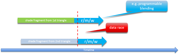
The usual unsynchronized memory access model in shaders: one pixel shader invocation is reading the latest color in the buffer, performing the blending math with it, and writing the new value to the buffer — but another pixel shader invocation may be accessing the same memory location at the same time, potentially making the color value read by the first invocation outdated, or overwriting its result, in a non-deterministic way, causing corruptions and flickering.
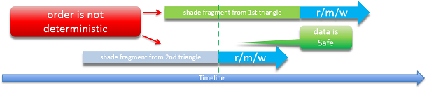
Even if atomicity is ensured, the order of the operations is still not deterministic — the fragment of the second overlapping triangle may randomly be accessing the data after the first, also causing flickering in algorithms where the order is important — such as alpha blending (surfaces from behind will be randomly appearing in front).
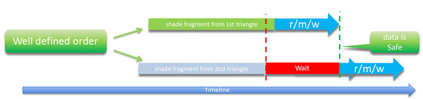
Both atomicity and ordering are provided by a rasterizer-ordered view — the read–modify–write operations for fragments of overlapping polygons will be ordered in the same order as in which the polygons they belong to are actually specified in the vertex/index/instance buffers and the command list. (images by Leigh Davies from the “Rasterizer Order Views 101: a Primer” article in the Intel Developer Zone)
A detailed explanation of the technology, as well as its various use cases, is given in the “Rasterizer Order Views 101: a Primer” article by Leigh Davies in the Intel Developer Zone. In Xenia, it allowed us to take full control of emulation of the output-merger logic of the Xbox 360’s GPU — to encode and decode all pixel formats, both color and depth, manually, down to every individual bit of the number. This allowed us to maximize accuracy of emulation of every pixel format, and also completely eliminate all the copying operation between host render targets, making the ROV-based pixel output path even faster than the old render target cache implementation — we’re simply not using host render targets at all.
However, with great power come many issues:
- All the early depth testing and hierarchical depth optimizations performed internally by the host GPU are unusable — since depth testing is done entirely by the pixel shader. In addition, hierarchical depth testing cannot be implemented as well even in the pixel shader — rasterizer-ordered views only offer interlocking within one pixel location, and access of the same memory from different pixel positions won’t be ordered, thus no “per-tile” structures can be used. The only way Xenia can do relatively “early” depth testing is by placing the code in the beginning of the shader, and returning early if it has failed — but the shader still gets scheduled and invoked, and this also causes all of the shader, including all the texture fetches, rather than only the end of it, to run in an interlocked way.
- The code for all the depth/stencil testing and blending, handling different sample counts, is very long and complex — often even longer than the original shader itself. This significantly increases the amount of time needed to process every pixel. In addition, long shaders take a very long time to compile in the driver — increasing stuttering when previously unseen materials are first drawn on the screen. On the AMD driver, crashes on shader compilation nearly impossible to debug also happen very often — only very few games (such as Doom 3: BFG Edition) can be played with the ROV pixel output path there.
- Rasterizer-ordered views are an optional feature in Direct3D. While Intel supports them on all of their Direct3D 12-compatible GPUs, Nvidia has only been supporting them since the second generation of the Maxwell microarchitecture. AMD was the most reluctant — the first GPUs supporting ROVs are the Vega series.
- On AMD hardware, the ROV implementation is also much slower compared to how rasterizer-ordered views work on Nvidia and AMD. In part for this reason, they’ve also refused to expose the pixel shader interlock functionality in Vulkan — leaving Direct3D the only API where they’re usable on their hardware (likely because ROV support is mandatory on the Direct3D feature level 12_1).
Due to these factors, even though the custom output-merger implementation based on rasterizer-ordered views provides the most accuracy, it can’t be the only emulation path that Xenia offers.
So we need a viable conventional host render target path. But the implementation that we had was still a rough prototype pretty much only designed to get something to work. One simplification that was used is that copying between the render targets and the eDRAM buffer was done through one more intermediate buffer — to write only a few generalized compute shaders: for 32-bit color formats, for 64-bit color, converting between 10.10.10.2 and 16.16.16.16 floating-point, for integer depth, and for floating-point depth. Whenever render target bindings were changed, the following operations were done:
- For each previously bound render target:
- Copy the render target data to an intermediate buffer in a linear layout (first the first row, then the second row, and so on — not very cache-efficient).
- Run the compute shader to copy the data from the intermediate buffer to the eDRAM buffer in the 80x16-tiled layout.
- For each new render target:
- Run the compute shader to copy from the eDRAM buffer to the intermediate buffer.
- Copy the new data from the intermediate buffer to the render target resource.
Each of these operations is moving a pretty large — multiple megabytes — amount of data. And all this sequence is done a lot of times per frame. For example, while clearing the depth buffer (using a 4x MSAA depth quad that we discussed previously) before drawing a color and depth pass, expensive copying may have to be done no less than 10 times — copy and compute to store the old render target (possibly more than one time if multiple render targets were bound previously), compute and copy to load before clearing, copy and compute to store after clearing, and compute and copy for two new render targets (color and depth). Apart from this, there were many limitations and flaws that this implementation had, and we’ll cover them in the next section.
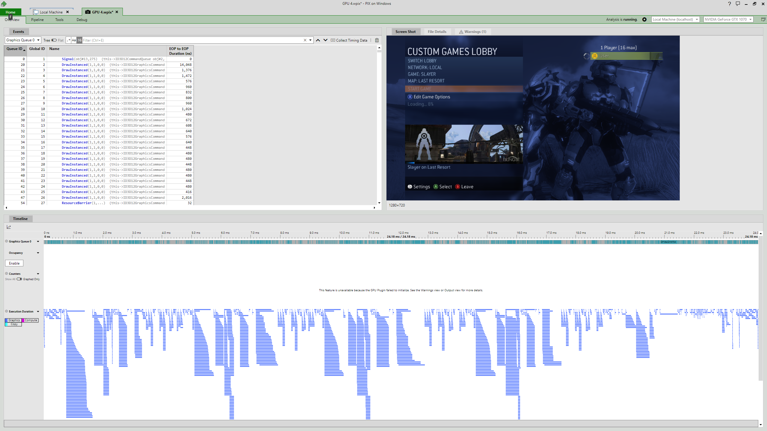
For now, take a look at the following timing capture from the Microsoft PIX graphics debugger:
Timings of a 80-millisecond (12 FPS) frame with the old render target cache — many long, badly parallelized operations (as render target copy and compute operations are preceded and followed by barriers) can be seen (Halo 3, by Bungie)
And we gotta go faster!
It’s a known fact that emulation naturally adds a lot of performance overhead. But here we’re dealing with an absolutely ridiculous amount of overhead — a game running at a 1152x640 resolution on a 2005 gaming console at 30 FPS, on a 2016 Nvidia GeForce GTX 1070, crawling at 12 FPS.
Before we start, compare the previous picture with the timing graph from the update that we have just released:
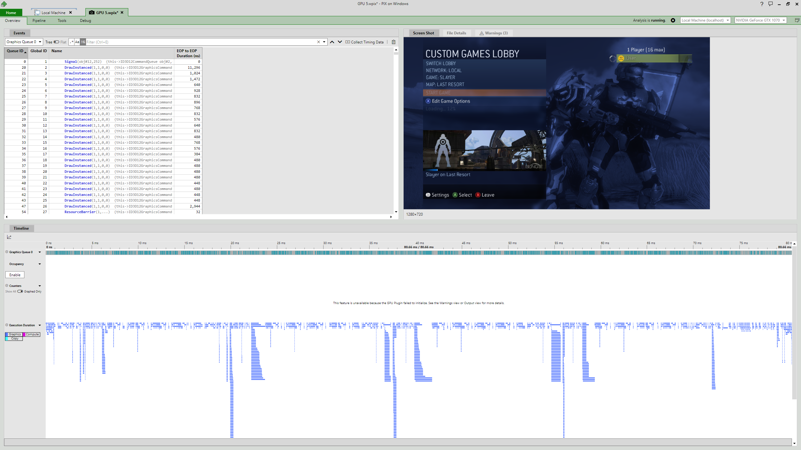
Timings of a frame with the new render target cache: 24 milliseconds (41 FPS) — 3.3x improvement and exceeding the game’s target framerate, with much better utilization of parallelism within the GPU (Halo 3, by Bungie)
Yes, we’re releasing a total rewrite of the render target cache that fixes many issues of the original implementation and hugely increases performance!
First of all, the entire brute-force logic of storing and loading the data after every single render target binding configuration change was replaced with a much more precise mechanism of “ownership transfers”. During the frame, it’s tracked which render targets were last using each eDRAM range (and thus owning it — containing the latest data in the range). So, copying (ownership transfer) is done only when a range is actually used with a different format, width or MSAA sample count. In many cases, switching the render target binding does not mean that you’re going to use all or most of eDRAM for a different purpose — consider this example:
- Draw surfaces without shadows to 1280x720 depth at 0–3600 KB and color at 3600–7200 KB in eDRAM.
- Fill a 512x512 (rounded to 80x16, being 560x512) shadow map for light 1 at 7200–8320 KB.
- Draw surfaces lit by light 1 to 1280x720 depth at 0–3600 KB and color at 3600–7200 KB.
- Fill another 512x512 shadow map, for light 2, at 7200–8320 KB.
- Draw surfaces lit by light 2 to 1280x720 depth at 0–3600 KB and color at 3600–7200 KB.
Here’s what would be happening in the old naïve render target cache implementation:
- Store the 1280x depth at 0 KB to the eDRAM buffer.
- Store the 1280x color at 3600 KB to the eDRAM buffer.
- Load the 560x depth at 7200 KB from the eDRAM buffer.
- Store the 560x depth at 7200 KB to the eDRAM buffer.
- Load the 1280x depth at 0 KB from the eDRAM buffer.
- Load the 1280x color at 3600 KB from the eDRAM buffer.
With the new logic, all that needs to be done from this list is:
- Nothing!
The shadow map in the 7200–8320 KB range of eDRAM does not overlap the depth buffer in 0–3600 KB and the color buffer in 3600–7200 KB — so there’s no need to do anything while switching between the shadow view and the main view, just like when doing the same in a usual PC game rendering pipeline. There still are issues with draws performed clipping to a viewport — again, the range touched by those draws has to be hugely overestimated — but once CPU vertex shader execution is added later to the emulator, it will be possible to determine the exact eDRAM extents for common cases of such draws, completely eliminating spurious overlaps and ownership transfers with no effect.
Other improvements come from the way copying between render targets itself is performed now. Previously, copying was done via the following path:
- Render target > linear buffer (CopyTextureRegion).
- Linear buffer > eDRAM buffer (compute).
- eDRAM buffer > linear buffer (compute).
- Linear buffer > render target (CopyTextureRegion).
Now, copying is done directly from one render target to another by drawing quads with a pixel shader reading directly from the previous render target. For every used combination of source and destination formats (color or depth/stencil, as well as the specific formats themselves) and MSAA sample counts, a pixel shader is generated at runtime, containing the code needed specifically to convert from one format and layout to another.
Apart from just moving less data in memory, there are various other advantages of this method:
- The CopyTextureRegion function of Direct3D 12 doesn’t allow copying between buffers and MSAA textures — so, with the previous render target cache implementation, Xenia was emulating MSAA as simple 1x2 or 2x2 supersampling — games with MSAA were pretty much always resolution-scaled internally, even though the final image was still 1280x720. This had many flaws — aside from just making pixel shading two or four times more heavy, it also did not allow 2x MSAA to anti-alias vertical edges (as scaling was only done along one axis, unlike in true 2x MSAA with diagonal samples), and post-processing effects also could result in a slightly blurred image because there was no 1:1 mapping between the source and the destination pixels. Now, Xenia supports true MSAA on the conventional host render target pixel output path, with a much smaller performance impact of MSAA usage.
- Another issue with CopyTextureRegion is that it only allows copying the entire image for depth/stencil buffers. As Xenia doesn’t always know the height of render targets needed, and also because when there are multiple render target bindings, their size must be the same on Direct3D 12, the host framebuffers are always created with a huge height — usually enough for storing the entire 10 MB of eDRAM. So, a lot of bandwidth was spent copying junk in the padding. Now, only the exact range ownership of which is being transferred needs to be copied.
- Copying raw image data to a framebuffer is also likely to destroy its internal compression and thus lead to slower rendering of the world. Drawing a quad, however, even with arbitrary depth output, is more friendly to compression. Specifically for spurious ownership transfer round-trips that may happen due to viewport-less draws, an additional safeguard was added to copying to depth buffers — the “not equal to” depth test is used, so if the ownership transfer doesn’t modify the depth in the end (results in the same values as the ones currently stored), it will also be more likely that the depth compression will not be destroyed because no writes will actually occur (this is a switchable option as it may cause bandwidth usage to increase).
- A memory barrier is necessary between copying, computing and drawing, heavily limiting the GPU’s ability to parallelize operations. The new method behaves very similar to simply drawing a textured surface in the game world — the only barrier needed is for the source framebuffer (so it can be read in a shader after it was written to as a render target), but in the future it can be even be moved earlier in the GPU timeline or even made asynchronous (via the split barriers functionality in Direct3D 12) so a pipeline stall may be avoided if the transfer source was last used a long time ago.
Except for the 10.10.10.2 floating-point color render target format that is emulated as 16.16.16.16 (but dropping the excess bits usually doesn’t have any visually noticeable consequences), ownership transfers between different formats are done non-destructively, bit-exactly, so round trips of data across formats are safe. For 16-bits-per-component and float32 formats, the actual bit representation is copied through an integer format view, so NaNs, denormal flushing and the interpretation of both -32767 and -32768 as -1.0 have no effect on copying. For the 24-bit floating-point depth format, whose encoding can store values up to 1.999…, a workaround is also used to overcome the clamping of depth values to 0–1 in Direct3D 12 (which doesn’t have an equivalent of VK_EXT_depth_range_unrestricted) — the 0–1 range of depth values is represented as 0–0.5 on the host, without precision loss as that’s simple exponent rebiasing, so all the possible encodings end up in the 0 to 0.999… range. The logic for preserving the full-precision 32-bit depth value for emulation of float24 is also preserved, but now, instead of maintaining two versions of the eDRAM buffer, two render targets may be “owning” each eDRAM range — the last render target of any format actually owning the range, and the last float24 render target used for that range.
One place where the new method has some unwanted additional overhead is copying to depth/stencil buffers — currently only AMD provides support for exporting the stencil reference value from pixel shaders (the SV_StencilRef output variable), and Intel also claiming to support it, but in our tests on UHD Graphics 630 it was simply ignored. So, on Nvidia and currently on Intel, stencil writing has to be done by drawing 8 large quads, significantly increasing the time it takes to transfer ownership of an eDRAM range to a depth/stencil render target. Nonetheless, this still pales in comparison with all the issues with a CopyTextureRegion-based approach.
With this architectural rework, Xenia now has a pretty solid and fast implementation of the console’s pixel output functionality! While it naturally has various accuracy flaws due to low flexibility of blending in the usual desktop GPU drawing pipeline (we’ve added a workaround for one of such issues though, and we’ll talk about it in the next section), it may be worth using in cases when more strict ROV-based implementation doesn’t provide the needed performance.
Here are some frame time comparisons between the old render target cache, the new one, and the fully custom ROV-based output-merger (tested on Nvidia GeForce GTX 1070, driver version 466.11, Windows 10 20H2, using the PIX timing capture of only the game GPU frame without presentation, by pressing F4 with PIX attached — CPU time is not included at all):
| Case | Old RT cache | New RT cache | ROV |
|---|---|---|---|
| Halo 3 custom games lobby (1152x640, 4xAA) |
79.8 ms (12.5 FPS) |
23.5 ms (42.6 FPS) 3.4x faster |
52.5 ms (19.0 FPS) |
| Halo 3 gameplay on Last Resort (1152x640, no AA) |
34.1 ms (29.3 FPS) |
13.6 ms (73.3 FPS) 2.5x faster |
23.8 ms (42.1 FPS) |
| Banjo-Kazooie: Nuts & Bolts menu (1280x720, 2xAA) |
31.6 ms (31.6 FPS) |
17.5 ms (57.1 FPS) 1.8x faster |
59.4 ms (16.8 FPS) |
| Sonic the Hedgehog gameplay (1280x720, 2xAA) |
19.5 ms (51.3 FPS) |
9.2 ms (109.2 FPS) 2.1x faster |
11.2 ms (89.3 FPS) |
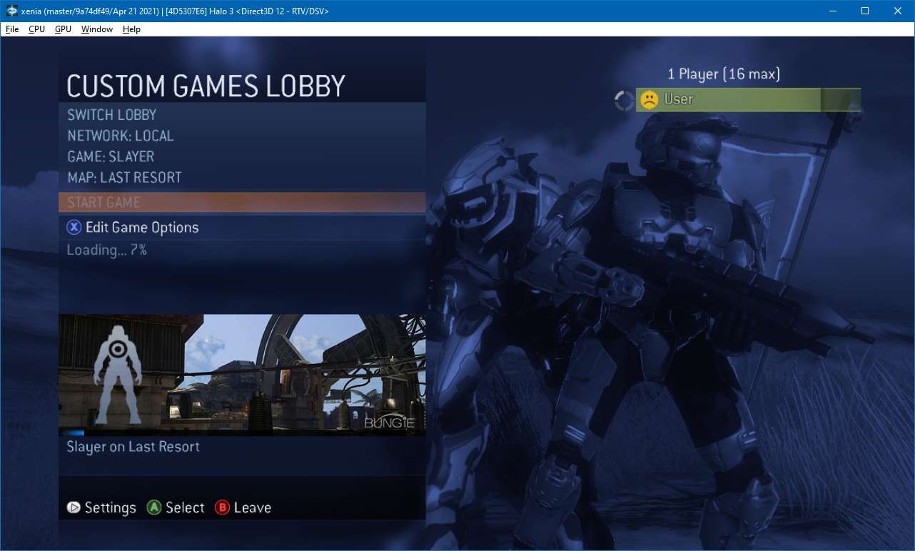
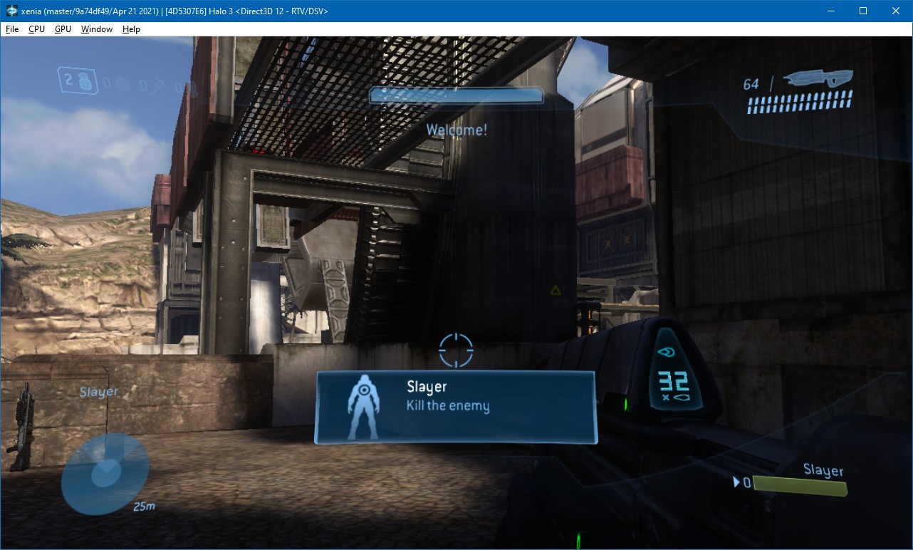
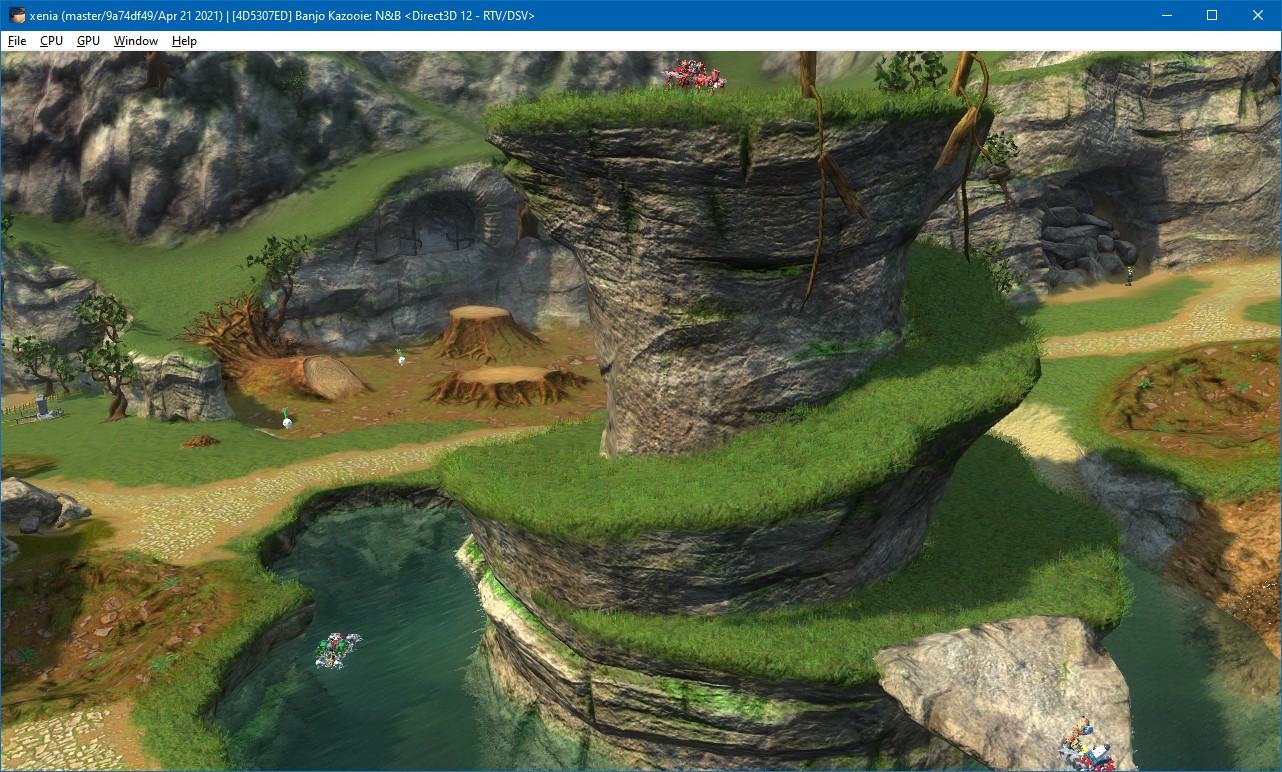
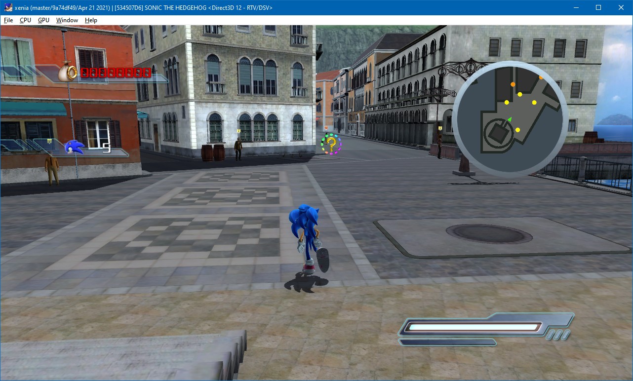
The gamma difficulty curve
Among the many places where “the Xbox 360 is not a PC” is the gamma curve used for framebuffers and textures by its GPU.
The response of a human eye is nonlinear — we’re much more sensitive to variation among dark tones than to changes in the bright range. If we turn on two light bulbs, the room will not look twice as bright to us. Monitors and TV screens take that into account, and also display the image in a nonlinear way. The color #808080 — or RGB 128, 128, 128 — may look twice as dimmer as #FFFFFF (255, 255, 255) — but doesn’t mean that the monitor is actually emitting twice as less light to display it.
This can be illustrated by the following test. If you are reading this page on a PC monitor with 100% page scale in your browser and system DPI settings, thus each image pixel matches a monitor pixel directly, move away from your screen and compare how bright the striped parts look compared to the solid rectangles in between:
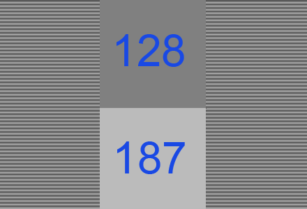
Perceptually vs. linearly half-bright value comparison (image by John Hable from the “Gamma and Mipmapping” post in the Filmic Games personal blog)
The left and right parts consist of alternating black (0, 0, 0) and white (255, 255, 255) lines — half of the pixels physically being black, half being white. This means that, on a CRT monitor, half the amount of photons (being a linear quantity) will be emitted compared to a solid white 255, 255, 255 rectangle. On an LCD monitor, it’s slightly more complex as backlight is still active for the black color, the amount of light emitted will be between that of a black 0, 0, 0 rectangle and of a white 255, 255, 255 one.
The solid rectangle on the top is colored 128, 128, 128 — half the 255, 255, 255 white. However, the bottom rectangle is visually much closer to the dithered pattern — but it has the 187, 187, 187 color instead. But why would a monitor, to display 128 — or half of 255 — not actually emit half the light it emits to display 255?
Compare these two gradients:
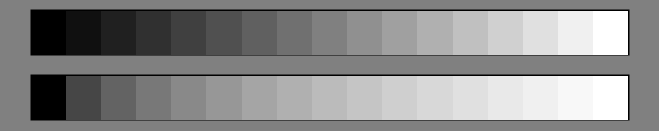
A gradient of colors in perceptually vs. linearly uniformly-spaced increments (image by Tavmjong Bah from the “Color Interpolation in SVG” personal blog post)
See how the top gradient looks much more uniform than the bottom one. The top gradient is in gamma color space — where brightness values we perceive are distributed uniformly, rather than the lightness values actually emitted, unlike in the bottom gradient.
Images are usually stored as pixels with equally-spaced discrete values of red, green and blue colors — 0/255, 1/255, 2/255, 3/255, and so on. The gradients displayed in the picture above are also an example of this — each rectangle representing values 0/17, 1/17, 2/17, and so on until fully white 17/17. But while 1/17 in the gamma space (in the upper gradient) is still very dark, in linear space (the lower gradient), it’s not possible to store any dark greys at all!
This is why it’s important that colors in fixed-point formats, such as raw 8 bits-per-channel images, or 7.8.7 (5.6.5, plus 2-bit factors) S3TC-compressed textures, are stored as gamma-space values. Framebuffers after tone mapping go directly or almost directly to the screen. Color textures — such as diffuse or albedo maps — are authored on monitors that display gamma-spaced images, and in normal in-game lighting conditions, also end up on the screen with brightness close than that in the original texture.
However, in shading of a 3D scene, lighting values inside the game world are calculated — using formulas based on real-life behavior of light. Thus, lighting has to be calculated using linear values — just like how the sum of light emitted by equal amounts of black and white pixels is halfway between the black level and white level in linear space in real life in the test above, lighting amounts are measured in linear space in the game world too.
This means that before the result is written to a fixed-point framebuffer, it needs to be converted from the linear space. Values from color textures participating in lighting need the reverse conversion — from gamma to linear. You might ask, why does the emulator have to bother about this at all, shouldn’t the game just do all the necessary conversion in shader code? But there’s one reason why that wouldn’t work properly.
Compare these two gradients:
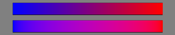
Gamma-space vs. linear-space gradient (image by Tavmjong Bah from the “Color Interpolation in SVG” personal blog post)
Here you can see bright blue being mixed with bright red. But in the upper gradient, you can see a relatively dark purple area in between, while the lower gradient stays much more uniformly bright along its range. This is because the upper gradient is interpolated in gamma space. At the left end, the color is 0, 0, 255 — or 100% of blue light emitted — and on the right, it’s 255, 0, 0 — 100% of red light emitted. But in the middle, we have half of 0, 0, 255 plus half of 255, 0, 0 — and that’s 128, 0, 128. However, as we know from the demonstration above, 128 does not result in 50% of the maximum light amount — rather, 128, 0, 128 only corresponds to 21% of red light and 21% of blue light in gamma space. The bottom gradient is in linear space — with 187, 0, 187 in the middle — which actually corresponds to 50% of red light and 50% of blue light, so you’re actually seeing purple consisting of 50% red and 50% black.
This is in part why blending has to be done in linear space. In a 3D scene, blending also corresponds to actual light calculations. When you’re drawing a glowing sign with additive blending, you’re adding the amount of light emitted by it to the frame buffer. One common way of implementing deferred lighting is by drawing the bounding volume (sphere or cone) of each lightbulb to run the shader for pixels on the screen corresponding to surfaces within the light’s falloff range — and the result is also written with additive blending to sum the amount of light from that lightbulb reflected by the surfaces with contribution of other light sources reaching them. Alpha blending is also used for transparent effects such as smoke — where the amount of light reflected by smoke particles is mixed with lighting behind the smoke with the factor of concentration of smoke particles in the volume in the game world that corresponds to the pixel. Screen-space ambient occlusion (SSAO) scales the amount of ambient light by the factor of how much of it is estimated to be able to reach a region around the point on the surface.
But blending with the current value in the framebuffer is done by the output-merger functionality of the GPU. This means that the fixed-function GPU hardware — not the game code — has to be responsible for conversion from linear to gamma, because before this conversion is done, another step needs to be done. The current value in the framebuffer needs to be converted from gamma to linear space before blending — but it’s only accessible by the output-merger stage of the pipeline, not the pixel shader. And then blending of linear values is done by the output-merger, and only after that the resulting value is converted to gamma.
On PC GPUs, the color space used to represent gamma values is sRGB, which is the color space also directly used on CRT monitors, and is the standard color space on Windows and assumed the default for images on the Internet unless a different one is specified in the image file. sRGB is close to a power 2.2 gamma curve, but also has a tiny linear portion for better representation of very small luminances. The exact formula defined by Direct3D to convert luminance x from linear to sRGB is 12.92 * x for x ≤ 0.0031308, and 1.055 * x1/2.4 - 0.055 for x > 0.0031308.
This is a pretty difficult formula to implement in hardware, and according to the OpenGL sRGB extension specification, it is expected to be implemented via lookup tables. But the Xbox 360’s output-merger logic is designed to be fast and wide — the eDRAM chip is able to process 32 color samples in one GPU clock. So, large hardwired lookup tables would likely take a lot of die space. Instead, the Xbox 360 uses a piecewise linear (PWL) approximation of the gamma curve, consisting of four linear parts, that is easy to implement in hardware using simple integer math.
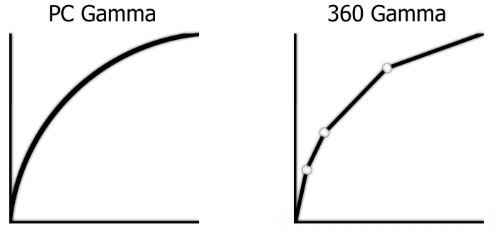
Comparison of gamma curves used by PC and Xbox 360 framebuffer and texture logic (image by Alex Vlachos from Valve Corporation from the “Post Processing in The Orange Box” presentation)
This difference is one of the difficulties of emulation — as this curve, as we said previously, is used in fixed-function parts of the GPU outside our control: output-merger and texture sampling functionality.
For textures, we’re doing the conversion in shaders after sampling the texture — generally the effects of texture filtering happening in gamma space rather than linear are not that significant, maybe with the exception of extreme cases not related to regular world textures. The possible alternatives are doing all the texture filtering in shaders manually (massive pixel shading performance overhead, especially for anisotropic filtering), pre-converting to linear while significantly increasing bit depth (big memory overhead, especially for compressed textures), or actually sampling as sRGB and converting from sRGB to PWL in the shader (not exact, but much closer to true PWL filtering).
With render targets, the effects of inaccurate gamma emulation are much more pronounced. First, even though the piecewise linear curve is an approximation of the sRGB curve, it is hugely different from the real sRGB curve — so we can’t just ignore this difference and just use the real sRGB wherever the game wants to use PWL.
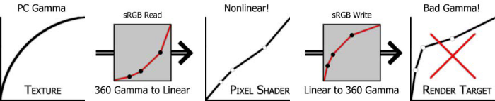
An example of effects of using a gamma curve different than the one data was created for or expected to be in, especially when conversions are chained (image by Alex Vlachos from Valve Corporation from the “Post Processing in The Orange Box” presentation)
So, the PWL gamma curve needs to be actually taken into account in render target logic as well. With the ROV-based output-merger implementation, these issues don’t exist by design as blending is handled entirely by our own code, and we are able to directly convert from PWL to linear before blending, and back before writing the result. But we still need a solution for the conventional host render target output path.
Previously, Xenia was simply converting the color value returned by the shader to PWL directly in shader code. However, this resulted in the issue that we began with — blending happens in gamma space in this case. This actually worked fine in many cases — generally gamma-space blending still looks believable enough, just different. And actually, early GPUs supporting sRGB conversion — the ones targeting Direct3D 9 — were also not doing blending in linear space, and were getting away with that mostly fine! Compare the translucent parts in the two screenshots of a Half-Life 2: Episode Two scene drawn with gamma-space and proper linear-space blending:
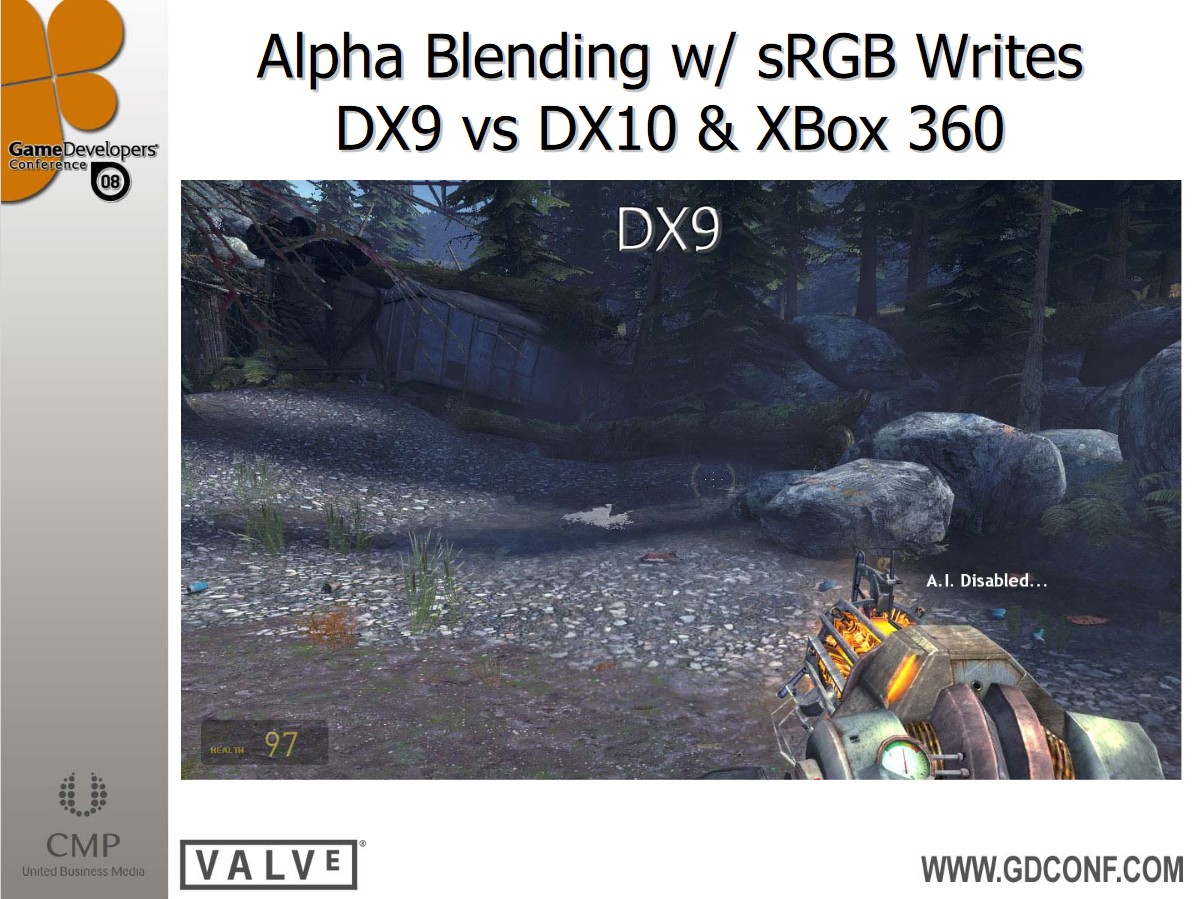
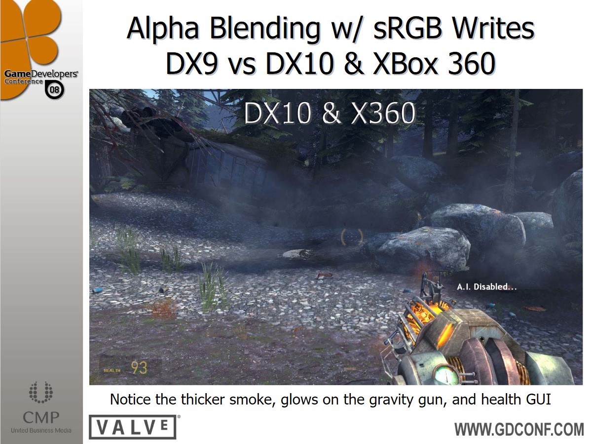
Comparison of gamma-space (DX9) and linear-space (DX10 & X360) blending — notice the thicker smoke, glows on the gravity gun, and health GUI (Half-Life 2: Episode Two, part of The Orange Box, by Valve Corporation, image by Alex Vlachos from Valve Corporation from the “Post Processing in The Orange Box” presentation)
However, there are cases where blending in the incorrect color space produces noticeably wrong results. One example is impact and footsteps decals in Halo 3. They are drawn with the source × destination + destination × source, or 2 × source × destination blending equation (where the source is the value returned by the shader, and the destination is the latest color in the framebuffer). This blending setup can be used to let the decal both lighten and darken the underlying surface — when the source is smaller than 0.5, the value in the framebuffer is darkened by scaling it by a value below 1, and when it’s above 0.5, the color is scaled by a value of 1 to 2, thus brightened. Source value 0.5 results in no change — the equation becomes 1 * destination.
But if the conversion is performed in the shader, the neutral 0.5 is not 0.5 in the blending anymore — it’s 0.75. This results in transparent areas being brightened instead — the equation becomes 1.5 * destination:
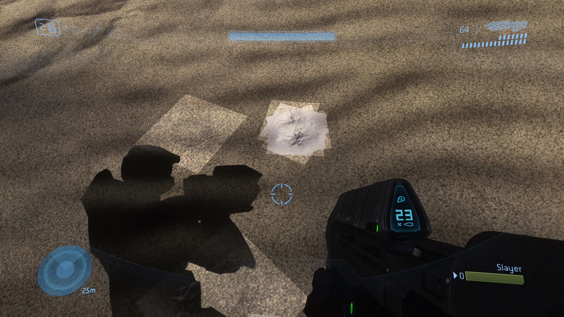
Incorrect blending when gamma conversion is done before blending (Halo 3, by Bungie)
This was one of the issues that were considered inherently unfixable in the old render target implementation. But the new update adds a workaround that works in certain games such as Halo 3: emulation of piecewise linear gamma with real sRGB, but only for render targets and render-to-texture — regular textures are still fetched as piecewise linear.
With the new option, the usual PC sRGB conversion is used for writing to render targets, thus blending is done properly in linear color space, and in the end it’s also written to 8-bit with increased precision for dark colors, though with a slightly different distribution of precision as opposed to that of PWL gamma. And when writing eDRAM data to textures in memory, the memory range is marked as containing render-to-texture data — and later, when reading gamma textures, it’s checked whether the texture was rendered to. For regular world textures, conversion is done from the usual PWL gamma — but render-to-texture data is converted from sRGB instead.
This gives a qualitatively correct result in cases when blending is involved:
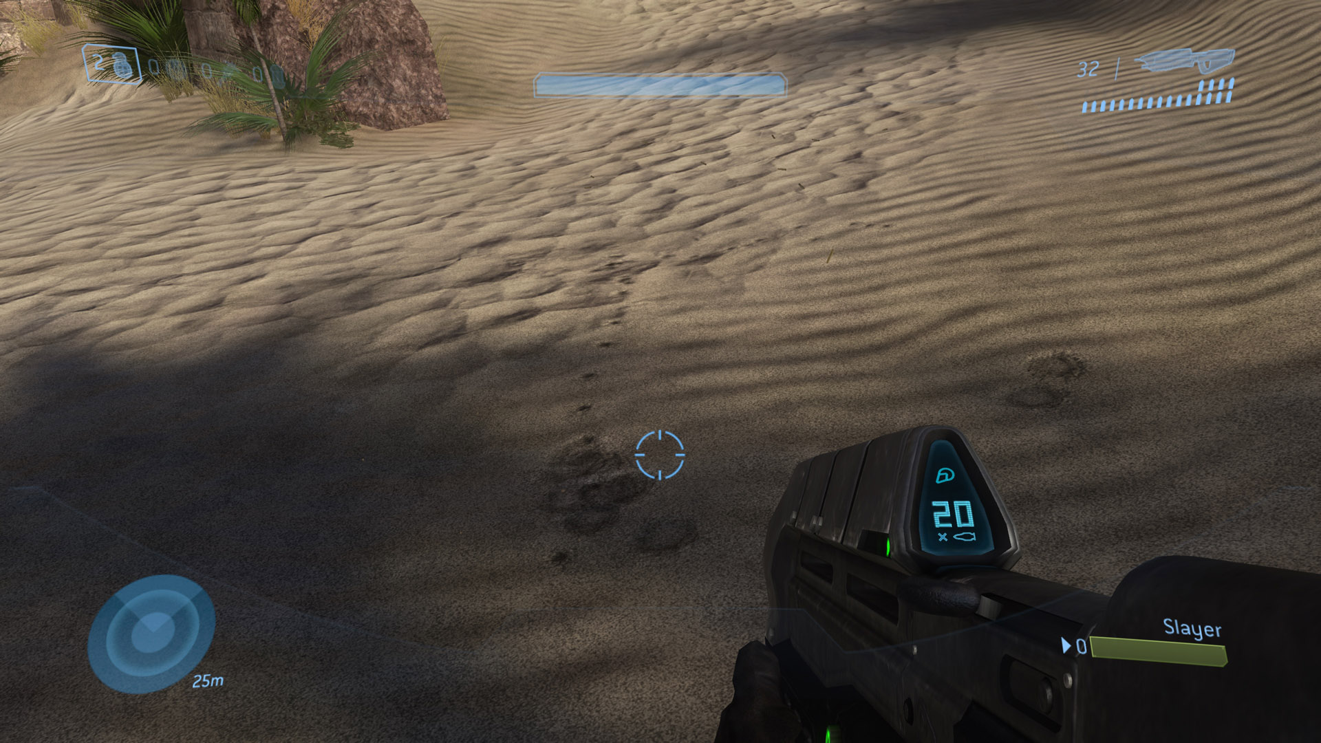
Emulation of piecewise linear gamma as sRGB in framebuffer writing and render-to-texture (Halo 3, by Bungie)
This new approach, however, only works in cases when the game only uses hardware gamma framebuffer writing and texture fetching. For various reasons (such as precision issues in the hardware implementation on the console, because 8-bits-per-component linear values are actually used in hardware in some cases, causing 1-2 bits of precision loss — as described in the “Post Processing in The Orange Box” and “CryENGINE 3: reaching the speed of light” presentations), games may be doing the conversion manually. And they may also be mixing hardware and software conversion — for example, draw the world with fixed-function gamma writing, but do post-processing with manual conversion. Since the game knows nothing about us using sRGB instead of the expected piecewise linear gamma, sometimes using the new option may produce incorrect results.
Incorrect colors caused by mixing true sRGB writes and the game’s manual PWL conversion — notice the brighter look and banding
Correct piecewise linear gamma throughout the entire frame rendering pipeline of the game without the new option (Portal, part of The Orange Box, by Valve Corporation)
Because of this, the new method of using sRGB for piecewise linear gamma is switchable with a configuration option and is disabled by default, since the impact of mixed gamma spaces is much more pronounced — the entire image may have incorrect colors — than that of incorrect blending, which is usually limited to translucent surfaces. The configuration option toggling the new behavior is gamma_render_target_as_srgb — true for using sRGB, false for piecewise linear gamma conversion before blending.
The Highest Density Pixels
One of the possibilities provided by emulators is making games playable not just in their original form on a different system, but also with an improved experience. Resolution scaling — the ability to render the game at a graphics resolution larger than the original — is a common feature provided by emulators. Xenia is among the emulators supporting increased rendering resolution. Previously it was, however, limited to 2x2 only — if the game natively uses 1280x720, Xenia renders it at 2560x1440.
The way it’s implemented does not contradict the low-level GPU memory emulation approach used in Xenia’s architecture — rather, the same concepts are applied, but with 1 pixel in the console’s memory corresponding to 2x2 pixels on the host, in both eDRAM (with tiles treated as 160x32 rather than 80x16) and the main RAM. In the latter, the original addresses used by the game are also preserved — we’re not going back to the old approximate approaches here.
This is accomplished via even more extensive use of sparse binding (also known as tiled resources) that are also used for 512 MB of the unscaled unified memory, but this feature actually requires sparse binding support now. Xenia maintains a 2 GB — 512 MB x 2x2 — virtual address space on the GPU for resolution-scaled render-to-texture data, but only allocates GPU physical memory for a tiny portion of all that address space — only for regions that render-to-texture has been done to. And if a texture touches any of those memory regions, its resolution-scaled version is loaded instead — from the 2 GB resolution-scaled space rather than the 512 MB unscaled unified memory one.
Previously, resolution scaling was also only implemented on the ROV-based pixel output path in Xenia. On the host-render-target-based path, however, it wasn’t, for various reasons, in both the performance and the maintenance aspects:
- MSAA was emulated as SSAA. 1280x720 scenes with 4x MSAA were already actually internally rendered at 2560x1440, except that this increased resolution only lasted until a resolve operation. With 2x2 resolution scaling, the internal resolution would be increased to a completely insane 5120x2880 — or 16 times more pixels than in the original image (almost twice as much as in 4K, which is 3840x2160, and contains 9 times more pixels than 720p).
- Performance was already abysmal due to excessive amounts of copying between render targets done in a very suboptimal way. 2x2 resolution scaling would quadruple all the pixel costs, including all the render target copying.
- The original render target code was a temporary basic implementation, planned to be rewritten from the very beginning, since it first started showing signs of low performance. When the much more accurate and fast ROV-based output-merger implementation was added, the old render target code started to be considered a largely unsupported fallback path.
Now, all these issues have been resolved, and the host render target cache is considered a first-class citizen implementation of the console’s output-merger code — moreover, with the new render target cache code, games run even faster than on the ROV pixel output path. So, resolution scaling is now fully supported on the conventional render target output path, without requiring ROV!
As resolution scaling is conceptually not a host-API-specific feature, the configuration variable for it has been renamed from d3d12_resolution_scale to draw_resolution_scale in the [GPU] section.
But this is not the only major change to resolution scaling — the update also introduces 3x3 resolution scaling that can be enabled by setting draw_resolution_scale to 3 in the configuration file. It’s supported on both the ROV and the non-ROV pixel output paths, and provides scaling to up to 4K (3840x2160)! Note that the performance hit of it is massive, and will generally provide a framerate below what can be considered “playable” — a very powerful GPU, somewhere on the Nvidia GeForce RTX 3080 level, is required to attain 30 FPS in most games. This will likely change in the future with various optimizations that we have ideas of, but for now that’s the performance to expect.
Check out various screenshots of games running with 3x3 resolutions scaling on Xenia:

Banjo-Kazooie: Nuts & Bolts, by Rare

Banjo-Kazooie: Nuts & Bolts, by Rare

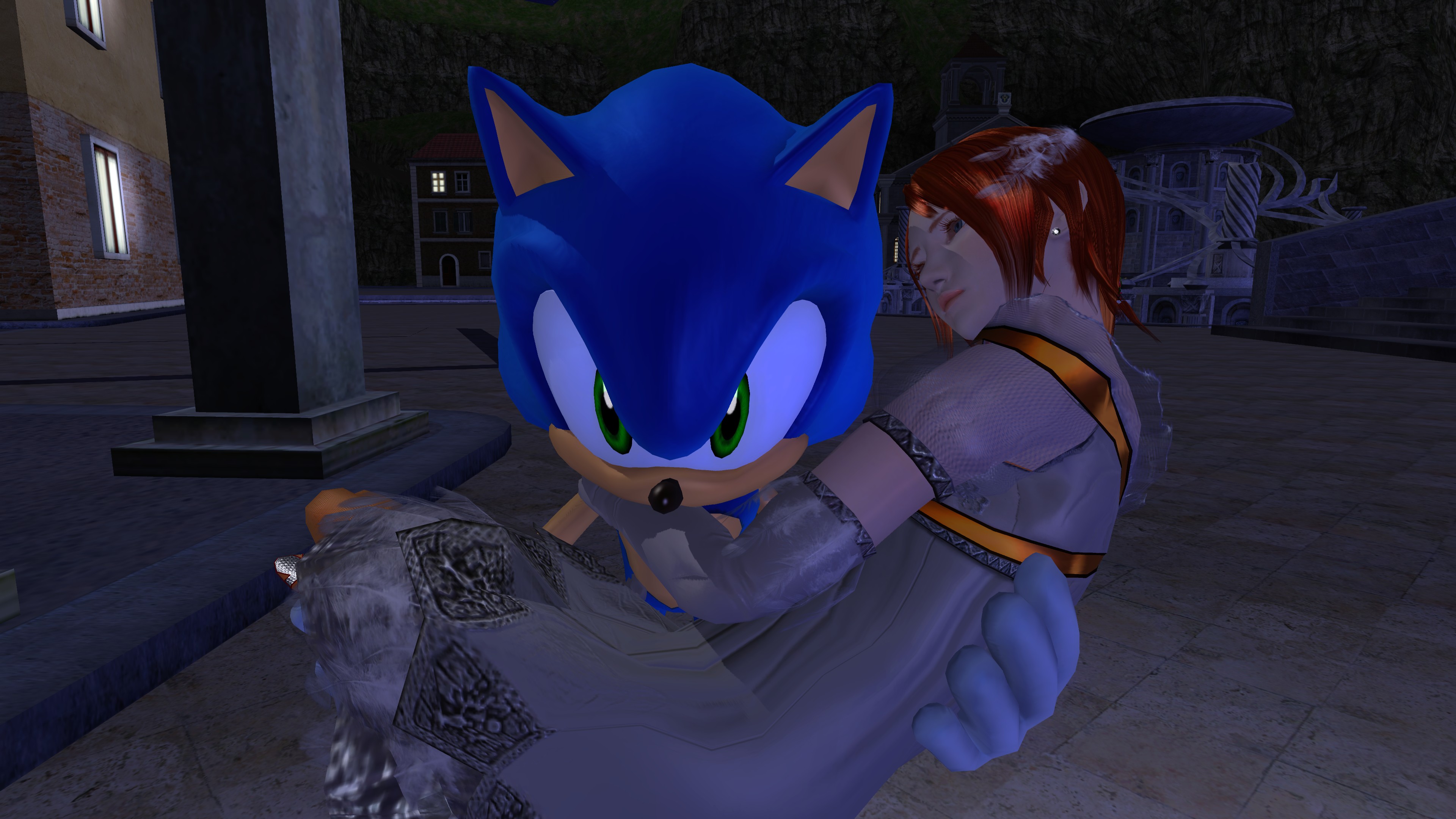
Sonic the Hedgehog, by Sonic Team and Sega

Sonic the Hedgehog, by Sonic Team and Sega
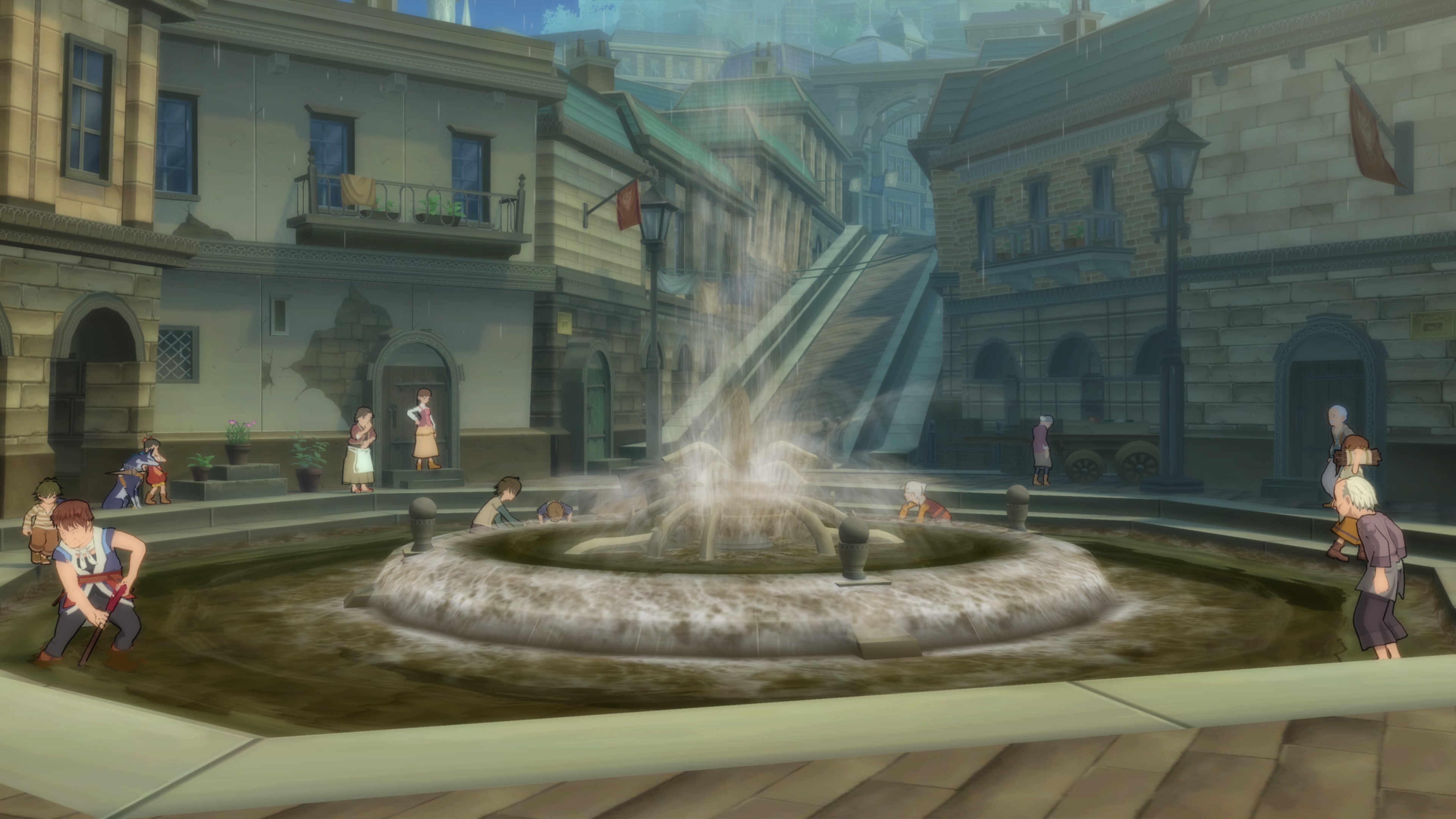
Tales of Vesperia, by Namco Tales Studio
An additional improvement to resolution scaling has also been made — the resolution scale is now taken into account in various texture fetching shader instructions, primarily in sampling pixel offsets and query of bilinear filtering weights. This fixes various “gathering”-based effects, such as shadow map filtering, bloom and blur when resolution scaling is used in some games. Here is an example of shadows in Halo 3 before and after the fix:
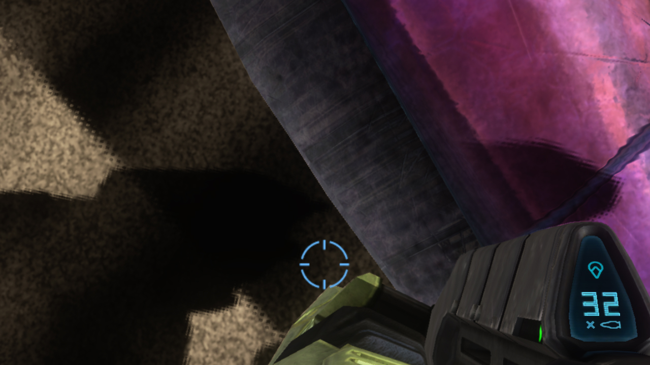
Shadow map filtering offsets and weights not corrected — notice the squares around the shadow
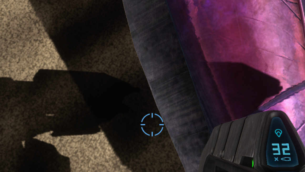
Correct shadow map with resolution scale applied to filtering (Halo 3, by Bungie)
Note that the game may still be calculating the same data manually in shader logic — in this case, it’s not aware of the resolution scaling being used, and the result will still be incorrect. For instance, in Halo 3, shadows are filtered correctly with the fix, but blur-related effects still produce grid patterns. This is outside our control, and cannot be fixed globally in an opaque way. Such cases would only be fixable by patching game shaders — such functionality is not available in Xenia yet. Because this correction may lead to undesirable results in some cases, it can be toggled with the draw_resolution_scaled_texture_offsets configuration option, which is enabled by default.
Keep in mind that resolution scaling is inherently a feature that can’t be done perfectly as the game is completely unaware of it, and it’s a mostly unsupported part of Xenia. There is a broad range of issues with it: unscaled size used in game shaders for gathering samples around some location, gather width being smaller than expected making effects like bloom or SSAO not as strong as they should be, blocky appearance if the game uses nearest-neighbor sampling for regular fullscreen textures or rounds the screen pixel position, gaps caused by half-pixel offset (which normally doesn’t affect pixel coverage, unless MSAA is used) becoming full-pixel (this is worked around to some extent — the second column/row of pixels is stretched into the first, but there are still various places where this issue surfaces), flashing screen or completely blank image caused by incorrect marking of memory ranges containing render-to-texture data.
TL;DR, configuration changes and ideas for the future
To summarize, this new update includes:
- New, faster and more accurate non-ROV render target cache:
- Massive optimization of copying eDRAM contents between host render targets — only copying data when needed, and in a much more straightforward way with significantly less bandwidth usage.
- Native MSAA emulation.
- An option for emulation of piecewise linear gamma as sRGB, for more correct translucent surface drawing —
gamma_render_target_as_srgb(disabled by default due to noticeably incorrect colors in certain games).
- Resolution scaling improvements:
- Now doesn’t require ROV.
- 3x3 scaling in addition to 2x2.
- An option for taking the resolution scale into account in cases of custom texture filtering in games —
draw_resolution_scaled_texture_offsets(enabled by default).
Important configuration option changes:
d3d12_edram_rovwas changed torender_target_path_d3d12, which may have the following values:- An empty string or any unknown value (default): Choose the option considered more optimal for your configuration. Currently the new render target cache (the non-ROV path) is always the default, due to a major speed advantage in most cases, unlike previously when the ROV path was the default at all times. Later, when (and if) the performance of the ROV path is made more optimal, it will be made the default again (at least on non-AMD configurations since our pixel output code is currently causing shader compilation crashes on AMD; it will also be re-enabled by default once most related crashes are fixed or worked around). If you’re experiencing accuracy flaws that look related to color formats, blending or hidden surface removal, especially if they weren’t there previously, change this option to “
rov”. rtv: force the conventional host render target cache (similar tod3d12_edram_rov = false).rov: force the rasterizer-ordered-views-based custom output-merger implementation if supported (similar tod3d12_edram_rov = true).
- An empty string or any unknown value (default): Choose the option considered more optimal for your configuration. Currently the new render target cache (the non-ROV path) is always the default, due to a major speed advantage in most cases, unlike previously when the ROV path was the default at all times. Later, when (and if) the performance of the ROV path is made more optimal, it will be made the default again (at least on non-AMD configurations since our pixel output code is currently causing shader compilation crashes on AMD; it will also be re-enabled by default once most related crashes are fixed or worked around). If you’re experiencing accuracy flaws that look related to color formats, blending or hidden surface removal, especially if they weren’t there previously, change this option to “
d3d12_resolution_scalewas renamed todraw_resolution_scale, supporting values of 1, 2 and 3.- New accuracy options covered above added:
gamma_render_target_as_srgb(only has effect on the non-ROV path).draw_resolution_scaled_texture_offsets(only has effect with resolution scaling).
There have been various other minor configuration option changes, but generally you should not change any values in the configuration file unless you know what exactly they are doing, and you’re sure that the option you’re changing has exactly the effect you’re trying to achieve. They are intended primarily for development of the emulator or for unusual edge cases.
Shader and pipeline state object cache will be reset and will need to be rebuilt by playing games again after this update as it contains significant modifications in render target bindings, among other things stored in the cache.
The latest build — as always — can be downloaded on the download page at xenia.jp, or from the download link in the #📝links-and-related-servers📝 channel on the Xenia Discord server.
In the future, various other things may be done to reduce GPU frame time on the emulator even further:
- For non-ROV: For draws without clipping, like clearing and other screen-space passes, execute the vertex shader (at least if it doesn’t include texture fetch since that would be extremely complex to implement) on the CPU to estimate the portion of the render target that would actually be involved in that draw.
- For non-ROV: When CPU vertex shader execution, try to detect Xbox 360’s Direct3D 9 clears and implement them via much faster and more compression-friendly fixed-function clearing on Direct3D 12.
- For ROV: Move various significant state parameters from conditionals in shaders to static parameters resolved at shader translation time for the current state. Currently, every single translated pixel shader contains code for all the somewhat-early and late depth/stencil testing and writing, all the color formats (both 32bpp and 64bpp), color write masking and all the possible blending equations, all for up to 4 MSAA samples. This results in lots of unneeded checks, jumps and possibly bad register allocation on the host, as well as extremely long pipeline state object creation times for shaders not yet in the cache. In most cases, only early depth testing and simple color writing in one format are enough.
- Pipeline barriers are currently placed simply right before resources are needed for some purpose. This causes excessive pipeline stalls if barriers are placed frequently. They can be combined in any place in the timeline between the last actual usages of the resources in the source states and the first usages in the destination states. Or, even better, use split barriers (or events, in Vulkan terminology) for all last and first usages in each state. The same may apply to memory shadow copy updates (it’s safe to update a range anywhere between the last and the next usage) and to texture conversion — these can be combined on the GPU timeline as well. Xenia already writes all host GPU commands through a “deferred” command list rather directly to an ID3D12GraphicsCommandList — this is done to be able to create pipeline state objects asynchronously, awaiting the completion before submission. However, this is the only usage of it in Xenia — in the regular situation when there are no pipeline state objects to create, the deferred command list only adds unnecessary overhead. It can be put to good use in the future to store resource dependencies and to place the needed split barriers. Or we can go even further and build a more abstract host “intermediate representation” of the frame, possibly with most of it shared between Direct3D 12 and Vulkan for even more straightforward barrier calculation and high-level reordering of memory shadow copy updates and texture loads, as well as building and executing Vulkan render passes and accumulating the size of the region modified by the render pass.
- To possibly reduce the host GPU’s local data share (LDS) usage, the information about the used interpolants — the actually used registers, the interpolation mode (center, centroid or flat), and possibly also the register to write the pixel’s position, faceness and point sprite UV coordinates to — may be baked in the translated shader code. Currently Xenia assumes that all possible 16 interpolants are passed between the vertex shader and the pixel shader, and also writes the system-generated parameters dynamically to the register specified at runtime, using lots of conditionals in the pixel shader. In reality, games usually pass far less parameters between the shader stages, wasting a lot of LDS space and reducing shader occupancy. This would require gathering the count or a mask of the interpolants used in the vertex shader (since only the vertex shader has interpolant registers marked as such — the pixel shader receives the data as initial values of general-purpose registers) and using it to determine what interpolants need to be a part of the input/output signature in the needed translations of the shaders, as well as for generating geometry shaders for emulating Xbox 360-specific primitive types (rectangle, point sprite) handling only the needed interpolants.
So, this summarizes the latest huge changes to emulation of the most complex and unique part of the Xbox 360’s graphics architecture, which provide more than 2x speed advantage over the previous implementation, as well as the challenges involved in emulation of it and the reasons behind architectural decisions made in Xenia. You can grab the build with the new update from the download page at xenia.jp. Become a member of our Patreon to support the development, join our Discord server to discuss all aspects of Xbox 360 emulation and to follow the development process, and stay tuned for more performance and accuracy improvements in the future — and never say never!